
Ink tank and ink supply system

a technology of ink supply system and ink tank, which is applied in printing and other directions, can solve the problems of increasing the number of ink tanks, increasing the frequency of tank replacement operations by users, and affecting the smooth and secure attachment of ink tanks, so as to speed up the ink supply and improve the attachment property of ink tanks

Active Publication Date: 2013-07-16
CANON KK
View PDF29 Cites 20 Cited by
  • Summary
  • Abstract
  • Description
  • Claims
  • Application Information

AI Technical Summary

Benefits of technology

[0017]An object of the present invention is to improve an attachment property of an ink tank having multiple ink supply ports and connectivity of an ink supply system, and thereby to contributing to development of a structure of a small ink tank which can meet the demand for multiple-color application and the demand for speeding up in ink supply.
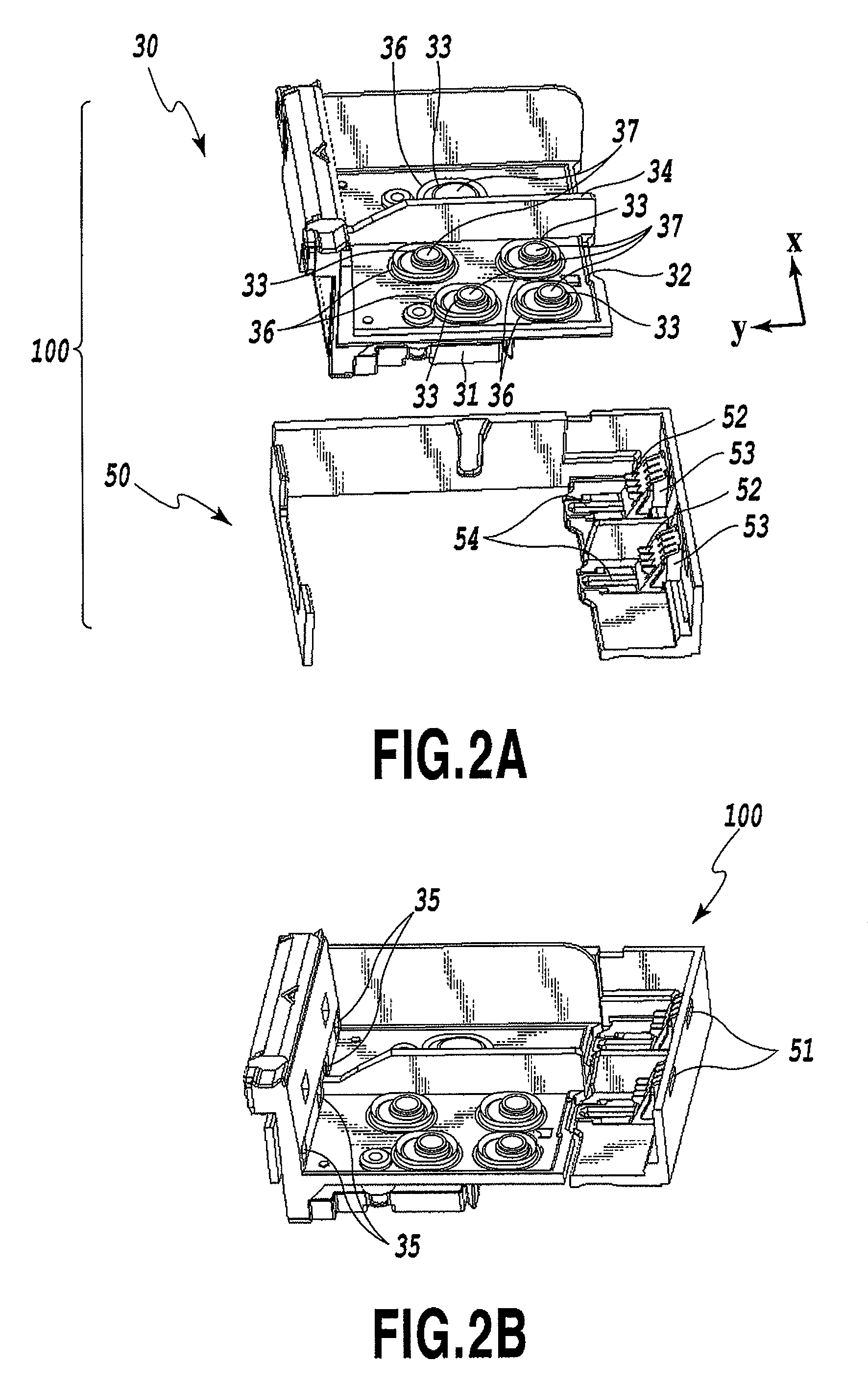
[0023]According to the present invention, multiple supply ports are appropriately spread and disposed on a face of a housing of an ink tank. Accordingly, when turning and attaching the ink tank, it is possible to avoid receiving a reactive force as an attaching force at one time at the ink receiving sections of the printing apparatus, and thereby to achieve stable attachment while suppressing excessive inclination of the tank at the time of attachment. In this way, it is possible to improve an attachment property of the ink tank and connectivity of an ink supply system.

Problems solved by technology

Such a configuration, however, causes an increase in the number of ink tanks, whereby the frequency of tank replacing operations by a user is increased.
In configuring an ink tank that can meet the demands for diversification in colors and for speeding up, the following problems are likely to occur.
Accordingly, the structure configured to simply arrange the ink supply ports two-dimensionally, as disclosed in Japanese Patent Laid-Open No. 10-286972, has a risk of hindering smooth and secure attachment of the ink tank (degradation in the attachment property).
Moreover, this structure also has a risk of hindering secure connection between the ink supply port and the ink receiving section (degradation in connectivity).
Meanwhile, the structure configured to arrange the ink supply ports linearly (Japanese Patent Laid-Open No. 2004-249710) incurs an increase in the number of ink color tones, i.e. an increase in the number of the ink supply ports and in the diameter of the ink supply ports associated with speeding up in ink supply, which leads to an increase in length of the ink tank in the direction of the arrangement of the ink supply ports, and thus hinders downsizing of the ink tank.

Method used


Image

  • Ink tank and ink supply system
  • Ink tank and ink supply system
  • Ink tank and ink supply system

Examples


Embodiment Construction

[0038]Now, the present invention will be described in detail with reference to the accompanying drawings.

[0039]It is to be noted that the term “ink” in this specification is assumed to include any liquid which may be used for formation of images, designs, patterns, and the like, a treatment of the printing medium, or the processing of ink (such as coagulation or insolubilization of a pigment in the ink to be applied to the printing medium), by being applied to a printing medium.

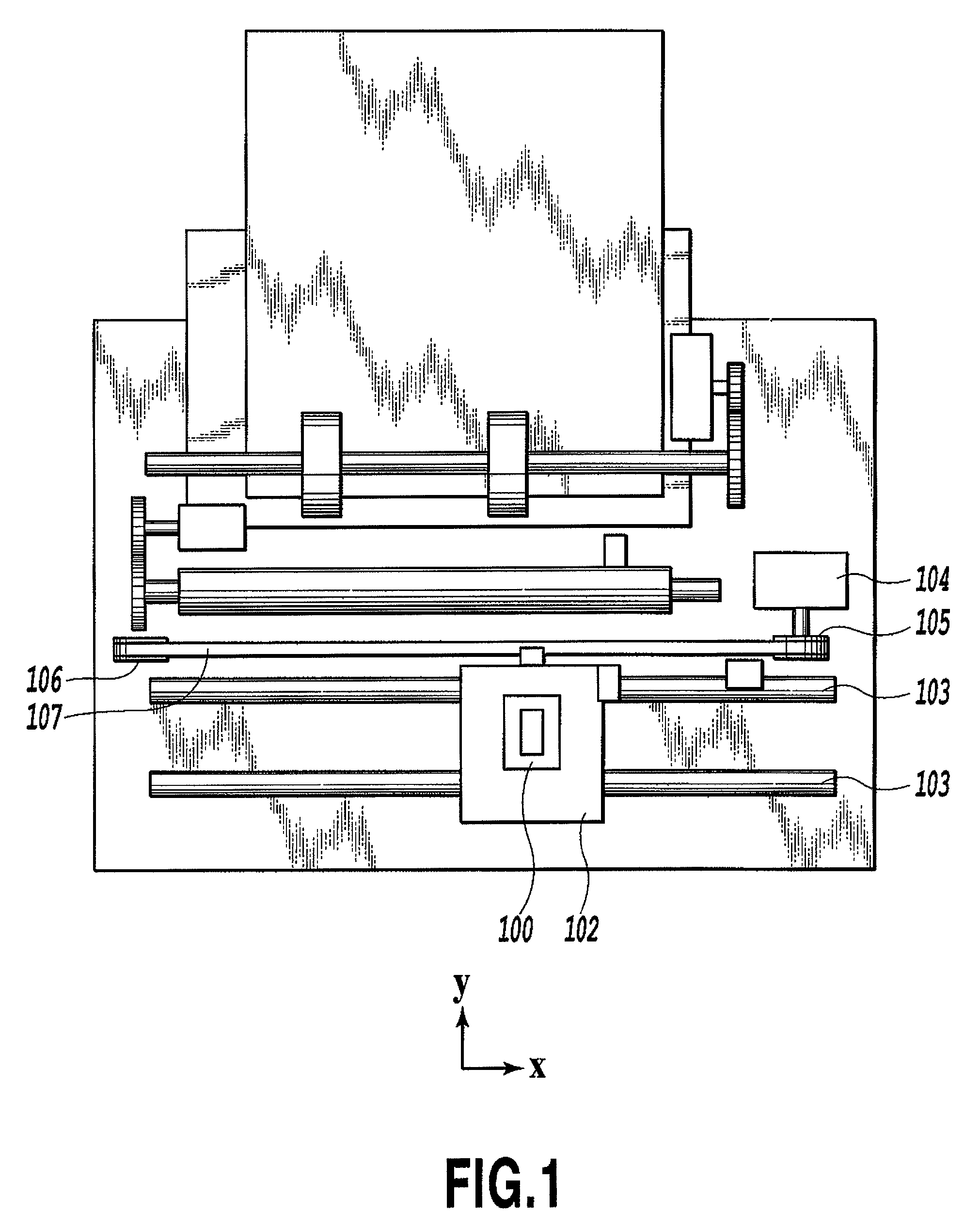
[0040]FIG. 1 is a schematic diagram showing an example of an inkjet printing apparatus to which the present invention can be applied.

[0041]In FIG. 1, an ink tank attachment section 100 is positioned and mounted on a carriage 102. The carriage 102 is guided and supported so as to be able to reciprocate in an x directions along a guide shaft 103 which is disposed on an apparatus body so as to extend in a main scanning direction. Moreover, the carriage 102 is driven by a main scanning motor 104 though transmissi...


PUM


Abstract

An ink tank is attachable to the attachment section by positioning first engagement sections at first fitting sections on the attachment section and then locking a second engagement section to a second fitting section of the attachment section by rotating the tank. The multiple supply ports are arranged on a bottom face of the tank such that the supply ports are on both sides of a center line in a width direction of the tank, and that distances between each of abutting centers configured to abut ink receiving parts of the attachment section, and the first engagement section side in a direction along a center line are mutually different. It is possible to avoid reception of a reactive force to the ink receiving parts at one time when rotating and attaching the tank, and to achieve stable attachment while suppressing excessive inclination of the tank at the time of attachment.

Description

BACKGROUND OF THE INVENTION[0001]1. Field of the Invention[0002]The present invention relates to an ink tank and an ink supply system, and, more specifically, to an ink tank and an ink supply system to be applied to an inkjet printing apparatus.[0003]2. Description of the Related Art[0004]Along the advance of image quality of printing in recent years, commonly employed in inkjet printing apparatuses is a method of increasing the number of ink colors used for printing in order to improve the image quality targeting for photographic image quality. A method of providing multiple tanks is widely used in a desktop printing apparatus, the tanks prepared respectively for different colors and being independently detachable. Such a configuration, however, causes an increase in the number of ink tanks, whereby the frequency of tank replacing operations by a user is increased. Moreover, as the ink tanks are provided independently, the wall thickness of each of the ink tanks has a great influen...

Claims


Application Information

Patent Timeline
Patent Type & Authority Patents(United States)
IPC IPC(8): B41J2/14B41J2/175
CPCB41J2/17513B41J2/1752B41J2/17523B41J2/17553
Inventor HAYASHI, HIROKITAKAHASHI, WATARUOGAWA, MASASHIKITABATAKE, KENJI
Owner CANON KK
Learn More