
Condensation dryer with a heat pump and recognition of an impermissible operating state and method for the operation thereof

a technology of condensation dryer and heat pump, which is applied in the direction of domestic cooling equipment, furnaces, instruments, etc., can solve the problems of substantial impairment of the effectiveness of the heat pump, inability to condense or fully condense the coolant, and insufficient drying process in certain circumstances, so as to reduce the heating power, the degree of dryness, and the drying process is very energy-intensive.

Inactive Publication Date: 2013-07-16
BSH BOSCH & SIEMENS HAUSGERAETE GMBH
View PDF24 Cites 17 Cited by
  • Summary
  • Abstract
  • Description
  • Claims
  • Application Information

AI Technical Summary

Benefits of technology

The invention provides a condensation dryer with a heat pump that can detect and prevent malfunctions by monitoring the temperature of the heat pump's coolant. The dryer uses a cooling device to regulate the temperature of the heat pump's components, particularly the compressor. The dryer is designed to operate within an optimum temperature range, which reduces energy waste and protects the heat pump. The invention allows for easy monitoring and detection of malfunctions, leading to timely maintenance and repair.

Problems solved by technology

That drying process is in certain circumstances very energy-intensive because the cooling-air current heated in the heat exchanger as the process air is cooled can in energy terms be lost to the process.
What is problematic about using a compressor-heat pump in the condensation dryer is the usually high temperature in the condenser, which for process reasons can result in its no longer being possible to condense or fully condense the coolant; the compressor will then have to be switched off and / or a substantial impairment in the heat pump's effectiveness will have to be accepted.
That problem is even worse when the compressor is supported by an additional heater in the process-air circuit to achieve faster heating of the process air and hence shorter drying times. Moreover, the circulating process air can be impeded by soiled air paths.
That can likewise cause the temperature of the coolant to rise.
Operating states of such kind can result in damage to the heat pump or other parts of the dryer and so are impermissible.
In any event, an impermissible operating state in a condensation dryer fitted with a heat pump can only be detected imprecisely in that way.

Method used


Image

  • Condensation dryer with a heat pump and recognition of an impermissible operating state and method for the operation thereof
  • Condensation dryer with a heat pump and recognition of an impermissible operating state and method for the operation thereof
  • Condensation dryer with a heat pump and recognition of an impermissible operating state and method for the operation thereof

Examples


first embodiment

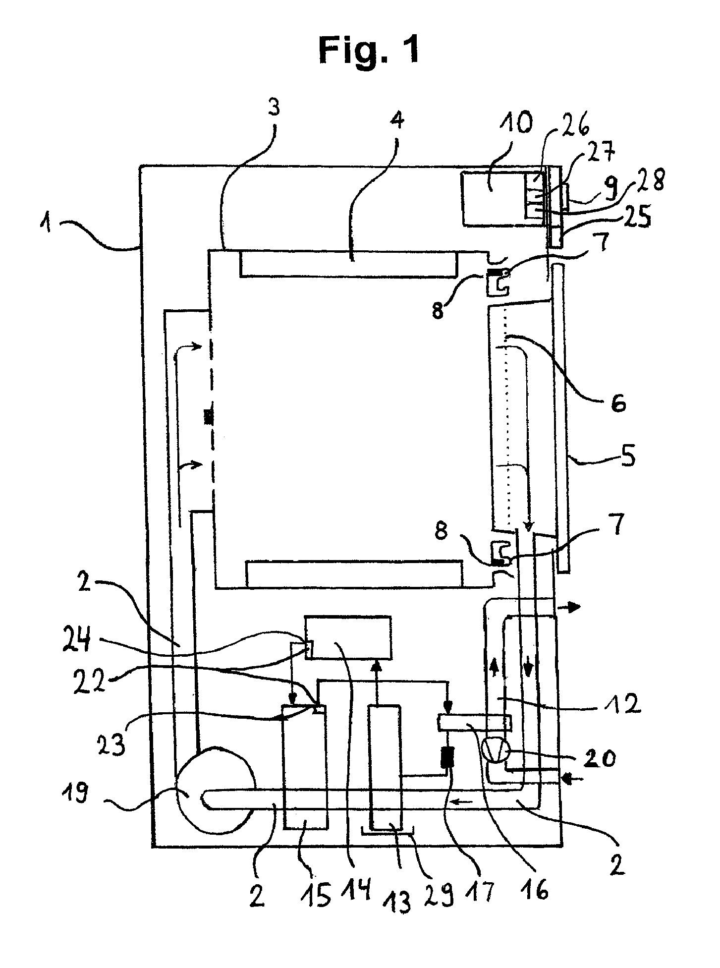
[0046]FIG. 1 shows a vertically sliced condensation dryer (abbreviated in the following to “dryer”) variant in which the process air is heated exclusively via the heat pump's condenser.

[0047]Dryer 1 shown in FIG. 1 has a drum, rotatable around a horizontal axis, as drying chamber 3 within which are secured carriers 4 for moving the laundry while the drum is rotating. Process air is ducted by means of a first fan 19 through a drum 3 and a heat pump 13, 14, 15, 17 in an air duct 2 in the closed circuit (process-air circuit 2). The process air heated in a condenser 15 of heat pump 13, 14, 15, 17 is cooled after passing through drum 3 and absorbing moisture and is heated again by condenser 15 after the moisture contained in the process air has been condensed. Heated air is therein ducted into drum 3 from behind, which is to say from a side of drum 3 opposite a door 5 through said drum's perforated base, hence making contact there with the laundry requiring to be dried, and flows throug...

second embodiment

[0053]FIG. 3 shows a vertical section of a condensation dryer (abbreviated in the following to “dryer”) variant in which there is an additional heat exchanger both in the heat pump and in the cooling-air duct of an air-air heat exchanger. An additional heater is also used in the embodiment variant shown in FIG. 3.

[0054]Dryer 1 shown in FIG. 3 has a drum, rotatable around a horizontal axis, as drying chamber 3 within which are secured carriers 4 for moving the laundry while the drum is rotating. Process air is ducted by means of a first fan 19 across a heater 18 through a drum 3, an air-air heat exchanger 11, 12, and a heat pump 13, 14, 15, 17 in an air duct 2 in the closed circuit (process-air circuit 2). The moist, warm process air is cooled after passing through drum 3 and is heated again after the moisture contained in the process air has been condensed. Air heated by heater 18 or, as the case may be, condenser 15 is therein ducted from behind, which is to say from a side of dru...

third embodiment

[0059]FIG. 5 is a schematic of the process-air circuit and heat-pump circuit for a third embodiment variant of the condensation dryer. In that embodiment variant additional heat exchanger 16 is located in cooling-air duct 12 on the side facing away from air-air heat exchanger 11, 12 of second fan 20. Heat exchanger 16 is thus located in the cooling air's intake region.


PUM


Abstract

A condensation dryer having a temperature sensor to measure a temperature of a coolant; a first comparator to determine a temperature difference between a first temperature of the coolant and a second temperature of the coolant that is measured after a period of time and to compare the temperature difference with a limiting temperature difference stored in a controller; a counter to ascertain a number of occurrences in which the temperature difference is greater than or equal to the limiting temperature difference; and a second comparator to compare the number of occurrences with a limiting number stored in the controller and to evaluate a number difference between the number of occurrences and the limiting number with respect to the presence of an impermissible operating state. A first impermissible operating state is indicated if the number difference is greater than or equal to a value stored in the controller.

Description

BACKGROUND OF THE INVENTION[0001]The invention relates to a condensation dryer having a heat pump and with detection of an impermissible operating state, and to a preferred method for operating the dryer.[0002]In a condensation dryer, air (what is termed process air) is ducted by a fan across a heater into a drum as a drying chamber containing damp laundry items. The hot air absorbs moisture from the laundry items requiring to be dried. Having passed through the drum, the then moist process air is ducted into a heat exchanger upstream of which as a rule a lint filter is connected. The moist process air is cooled in said heat exchanger (for example an air-air heat exchanger or a heat pump's heat sink) so that the water contained in the moist process air condenses. The condensed water is then generally collected in a suitable container and the cooled and dried air ducted back to the heater (which may be a heat pump's heat source) and then to the drum.[0003]That drying process is in ce...

Claims


Application Information

Patent Timeline
IPC IPC(8): F26B3/00
CPCD06F58/206D06F2202/04D06F2103/52
Inventor NAWROT, THOMASNEHRING, ULRICH
Owner BSH BOSCH & SIEMENS HAUSGERAETE GMBH
Learn More