Electrolytic solution for nonaqueous electrolyte secondary battery and nonaqueous electrolyte secondary battery using the electrolytic solution
a technology of electrolytic solution and nonaqueous electrolyte, which is applied in the direction of non-aqueous electrolyte cells, cell components, cell component details, etc., can solve the problems of reducing the voltage of the battery, leaking electrolytic solution, and reducing the discharge capacity of each battery
- Summary
- Abstract
- Description
- Claims
- Application Information
AI Technical Summary
Benefits of technology
Problems solved by technology
Method used
Image
Examples
production examples
Preparation of Electrolytic Solutions A to L
[0053]Electrolytic solutions A to L were each prepared in accordance with the composition shown in Table 1 by dissolving lithium perfluoromethyl sulfonylimide as a solute in a solvent so that a concentration might be 1 mol / L.
[0054]It should be noted that compounds represented by abbreviations for solvents in Table 1 are as described below.
[0055]TEG: tetraethylene glycol dimethyl ether
[0056]DEE: ethylene glycol diethyl ether
[0057]DME: ethylene glycol dimethyl ether
[0058]DIG: diethylene glycol dimethyl ether
[0059]EGEE: ethylene glycol monoethyl ether
[0060]
TABLE 1Solvent composition ofelectrolytic solutionEGEEElectrolytic solution(volume ratio)(vol %)ATEG / DEE = 50 / 50—BTEG / DME = 50 / 50—CTEG / DEE = 80 / 20—DTEG / DEE = 75 / 25—ETEG / DEE = 67 / 33—FTEG / DEE = 33 / 67—GTEG / DEE = 25 / 75—HTEG / DEE = 20 / 80—ITEG = 100—JDEE = 100—KTEG / DIG = 50 / 50—LTEG / DEE = 50 / 500.5
example 9 and reference examples 1 to 4
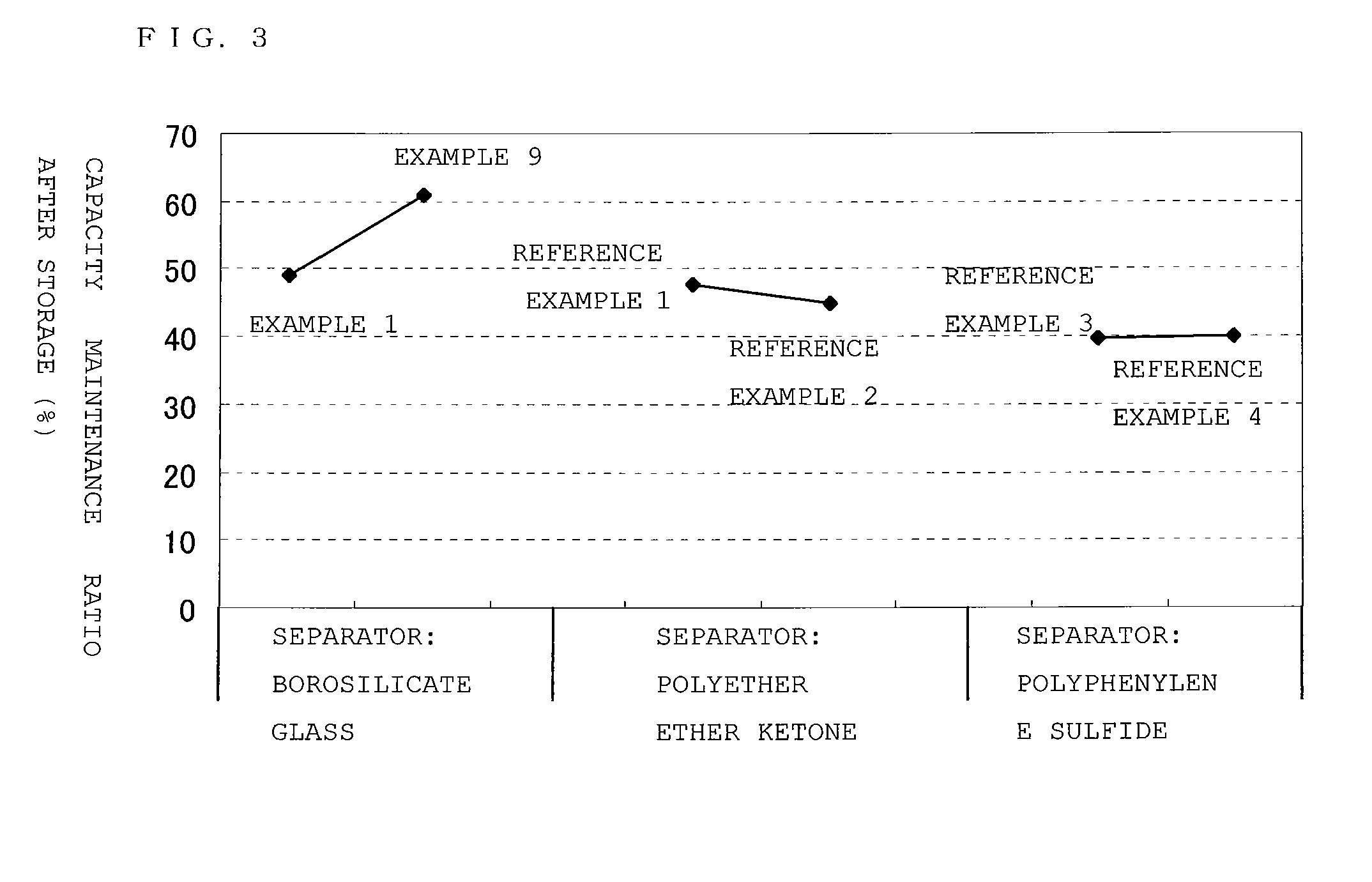
[0072]Reflow secondary batteries were each obtained in the same manner as in Example 1 except that an electrolytic solution shown in Table 3 was used as the electrolytic solution, and a material shown in Table 3 was used in the separator. The capacity maintenance ratios after storage of the resultant reflow secondary batteries were determined, and the results were shown in Table 3.
[0073]
TABLE 3CapacityElectrolyticmaintenance ratiosolutionSeparator materialafter storage (%)Example 1ABorosilicate glass49.2Example 9LBorosilicate glass61.1ReferenceAPolyether ether ketone47.6Example 1ReferenceLPolyether ether ketone44.9Example 2ReferenceAPolyphenylene sulfide39.7Example 3ReferenceLPolyphenylene sulfide40.2Example 4
[0074]FIG. 3 is a graph illustrating the capacity maintenance ratios after storage in Examples 1 and 9, and Reference Examples 1 to 4. It should be noted that, in FIG. 3, the axis of ordinate indicates the capacity maintenance ratio after storage and the axis of abscissa is div...
PUM
| Property | Measurement | Unit |
|---|---|---|
| temperature | aaaaa | aaaaa |
| boiling point | aaaaa | aaaaa |
| heat distortion temperature | aaaaa | aaaaa |
Abstract
Description
Claims
Application Information
 - R&D
- Intellectual Property
- Life Sciences
- Materials
- Tech Scout
- Unparalleled Data Quality
- Higher Quality Content
- 60% Fewer Hallucinations
Browse by: Latest US Patents, China's latest patents, Technical Efficacy Thesaurus, Application Domain, Technology Topic, Popular Technical Reports.
© 2025 PatSnap. All rights reserved.Legal|Privacy policy|Modern Slavery Act Transparency Statement|Sitemap|About US| Contact US: help@patsnap.com


