Magnet pole for magnetic levitation vehicles, and method for the production thereof

a technology of magnet poles and vehicles, applied in the direction of magnet materials, dynamo-electric machines, cores/yokes, etc., can solve the problems of high temperature of coils, high mechanical stress on protective layers, and large elongation at tear of protective layers which are typically used and fixedly connected to coils at critical points. , to achieve the effect of improving the environmental resistance of the magnet pole, reducing the tearing of the protective layer in the critical regions, and increasing the service life of the magn

Active Publication Date: 2013-07-02
THYSSENKRUPP TRANSRAPID
View PDF13 Cites 0 Cited by
  • Summary
  • Abstract
  • Description
  • Claims
  • Application Information

AI Technical Summary

Benefits of technology

[0007]Proceeding therefrom, the technical problem addressed by the present invention is that of designing the magnet pole of the type in question such that tearing of the protective layer in the critical regions is reduced, thereby markedly increasing the service life of the magnet pole. In addition, a method for the production of the magnet pole is provided.
[0008]A marked improvement of the environmental resistance of the magnet poles, with regard to moisture in particular, is achieved by way of the invention. Obviously, the elastic section of the protective layer, which is provided in the critical regions, can compensate for the different thermal expansions resulting from the different expansion coefficients and thereby prevent the gaps and tears described above.

Problems solved by technology

During operation of such magnet poles, relatively high currents are conducted through the coils, thereby causing the coils to heat up to a great extent.
As a result, there is a risk that the elongation at tear of the protective layers which are typically used and which are fixedly connected to the coils will be greatly exceeded at critical points.
The protective layers are subject to particularly strong mechanical stresses in the critical regions when the electromagnets equipped with the magnet poles are switched on and off in cycles, as is the case, for example, with support magnets of a magnetic levitation vehicle due to the constant switch between vehicle operation and pauses in vehicle operation.
As a result, cracks forms in the protective layers and / or gaps between the circumferential surfaces of the iron cores and the end faces of the protective layers adjacent thereto, thereby permitting moisture to enter the interior of the magnet poles and, over time, destroy the insulation between the coils and the iron cores.
Leakage currents induced as a result render the magnet poles unusable if they reach a certain size.

Method used


Image

  • Magnet pole for magnetic levitation vehicles, and method for the production thereof
  • Magnet pole for magnetic levitation vehicles, and method for the production thereof
  • Magnet pole for magnetic levitation vehicles, and method for the production thereof

Examples


Embodiment Construction

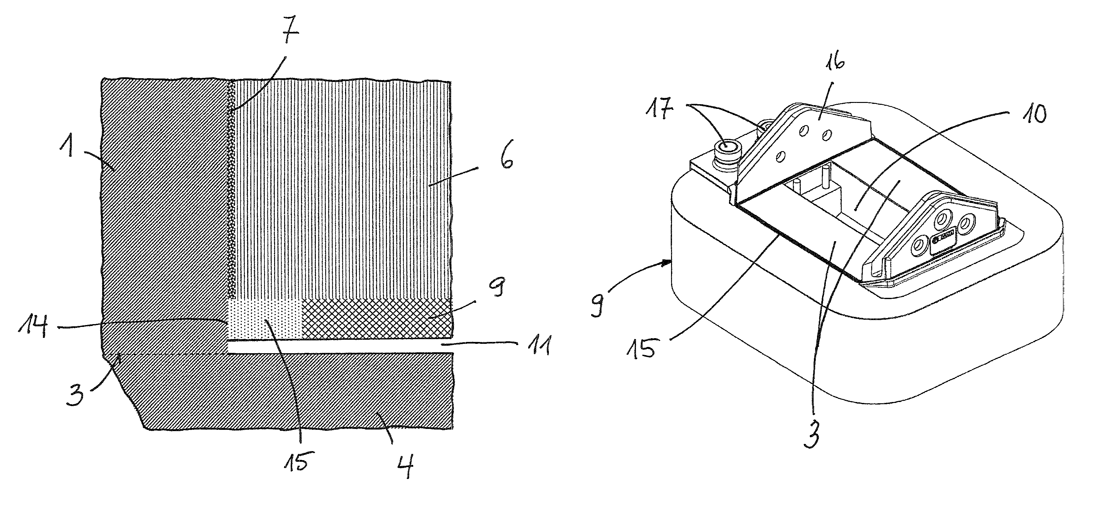
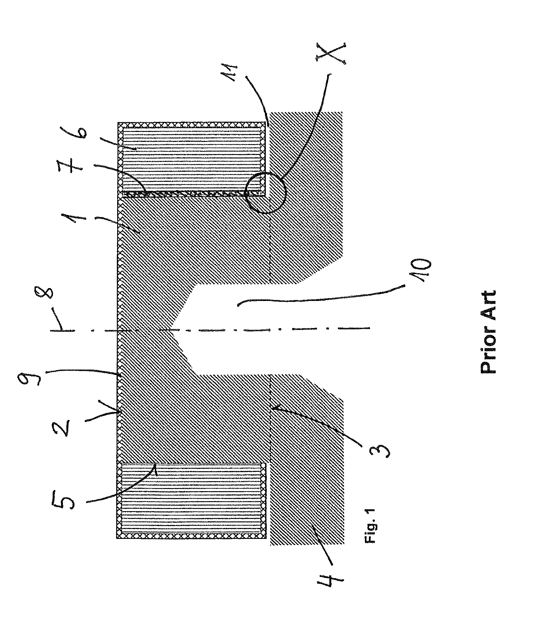
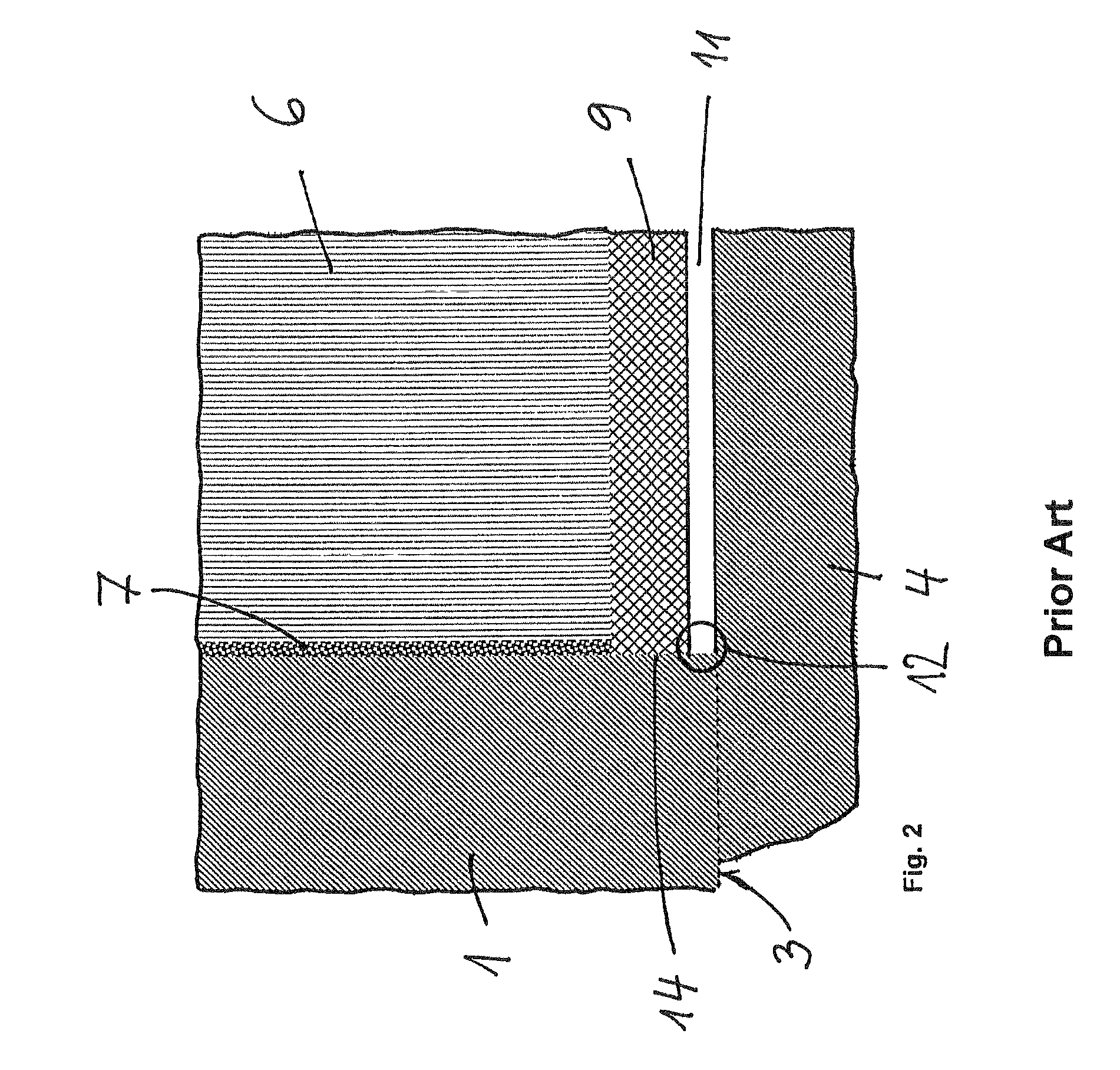
[0014]FIG. 1 shows a known magnet pole which is used, for example, in a magnet system for a support magnet in a magnetic levitation vehicle. It contains a ferromagnetic iron core 1 composed of electrical steel sheets, which is equipped with a pole surface 2 on an upper side, a contact surface 3 for a magnet rear side 4 on a lower side, and, on the circumference thereof, with a circumferential surface 5 disposed between the upper pole surface 2 and the lower contact surface 3. A coil 6 in the form of a disk is wound onto the circumferential surface 5, which comprises, for example, a conductive strip which is made of aluminum or another advantageous, highly electrically conductive material and is applied in a plurality of layers. An intermediate layer 7 made of insulating material, e.g. a suitable plastic, which is depicted in FIG. 1 only in the right-hand part but which actually encloses the iron core 1, is disposed between the iron core 1 and the coil 6, and serves, in particular, t...


PUM

PropertyMeasurementUnit
elasticaaaaaaaaaa
thermalaaaaaaaaaa
mechanical stressesaaaaaaaaaa

Abstract

A magnet pole for magnetic levitation vehicles includes an iron core (1) having an upper pole surface (2), a lower contact surface (3) for a magnet rear side (4) and a circumferential surface (5) disposed between the pole surface (2) and the contact surface (3). A coil (6) is applied onto the circumferential surface (5) of the iron core (1). An intermediate layer is made of an electrically insulating material, which is disposed between the circumferential surface (5) and the coil (6). A protective layer (9) encapsulates the coil (6). At least the pole surface (2) of the iron core (1) is made of a hard material and abuts the circumferential surface (5) in a lower region of the iron core (1). The protective layer (9) contains a section (15) made of an elastic material in a region adjacent to the circumferential surface (5).

Description

CROSS-REFERENCE[0001]The invention described and claimed hereinbelow is also described in PCT / EP2010 / 004636, filed on Jul. 29, 2010 and DE 10 2009 038 559.2, filed on Aug. 28, 2009. This German Patent Application, whose subject matter is incorporated here by reference, provides the basis for a claim of priority of invention under 35 U.S.C. 119 (a)-(d).BACKGROUND OF THE INVENTION[0002]The invention relates to a magnet pole of the type, and a method for the production thereof.[0003]Magnet poles of the stated type are used in magnetic levitation vehicles and, in this case, in magnet systems of support magnets, for example. They mainly comprise an iron core and a coil in the form of a strip of aluminum or the like, which has been wound onto the circumferential surface of the iron core (e.g. DE 197 03 497 A1, DE 10 2004 011 941 A1). For protection against environmental influences such as moisture, the magnet poles are also encapsulated in a protective layer made of a plastic which compri...

Claims


Application Information

Patent Timeline
Patent Type & Authority Patents(United States)
IPC IPC(8): H01F7/00H01F41/00
CPCB60L13/04H02K41/02H01F1/14
Inventor BUGIEL, PETERDIEKMANN, ANDREASKRAEMER, JOACHIMTSCHADA, DANIELZHENG, QINGHUA
Owner THYSSENKRUPP TRANSRAPID
Why Eureka
Try Eureka