Transport unit and set for securing cargo items

a technology for transporting units and cargo items, applied in the field of transporting units, can solve the problems of unfavorable ratio of transport volume required to actual transport volume provided, unfavorable ratio of gross/net, and unsuitability of transport units for transport devices with a limited width

Active Publication Date: 2013-07-02
SONOCO DEV INC
View PDF24 Cites 6 Cited by
  • Summary
  • Abstract
  • Description
  • Claims
  • Application Information

AI Technical Summary

Benefits of technology

[0011]It is an object of the present invention to improve a transport unit of the known type, so that it is suitable for transporting layers essentially arranged precisely on top of one another and including identical numbers of cargo items, and so that a fixation of the cargo items is provided in a simple manner. Thus furthermore, a respective set shall be provided for securing the cargo items.
[0016]It is also advantageous, that the height of the tension device, thus the dimension in vertical direction can be selected small, so that the height of the transport unit only slightly deviates from the sum of the cargo items arranged on top of one another, which provides a compact transport unit.
[0021]The fixation of the cargo items of one layer according to the invention provides an extremely simple, flexible and quick option to assemble a transport unit.
[0023]It is advantageous when the stop elements are configured wedge-shaped and have contact surfaces which enclose an angle of at least 45°, preferably at least 50° with one another. Thus, the stop surfaces can be configured as straight surfaces or they also can be configured from slightly cambered surfaces.
[0028]The tension device advantageously includes respective grooves on the longitudinal sides oriented towards the cargo items; this means the tension device includes an H-shaped cross-section. Thus, it is furthermore advantageous when cushions are arranged within the grooves, wherein the cushions are respectively oriented towards the enveloping surfaces of the cargo items. This way it is mostly avoided that impressions are formed in the cargo items in the portion of the tension devices due to the relatively high punctiform load. The cushion can be made e.g. from rubber or other suitable materials, wherein furthermore a positive effect is achieved for a rubber cushion in that a friction between the cargo items and the tension devices is prevented and thus a sliding of the cargo items is prevented.
[0031]It is advantageous when the tension device and the stop elements are configured as plastic injection molded components.

Problems solved by technology

The unfavorable ratio of transport volume required to actual transport volume provided.
Thus, the ratio gross / net, which becomes even more unfavorable as more layers are stacked on top of one another, is a disadvantage of the known transport units identified above.
Though cargo items can be transported in this manner with significantly better gross / net ratio, however the width of the transport unit thus obtained is larger due to the second and possibly also fourth layer laterally protruding beyond the lowest layer, so that the transport unit is not suitable for transport devices with a limited width.
However, since differently configured pallets are required for different roll diameters a plurality of different pallets has to be stored, which causes large storage space requirements.
Furthermore, this type of arranging cargo items is detrimental, since the diameters typically do not fit exactly into the concave indentations of the pallets, so that the cargo items have certain clearance in the indentations and can rock slightly.
Consequently, a transport unit thus configured is not as stable as a unit configured as a block.
Eventually, it is also detrimental for the pallets recited supra that the positioning is time-consuming and they cannot be sufficiently cleaned from dust and contamination, which is in particular detrimental when transporting sensitive materials.

Method used


Image

  • Transport unit and set for securing cargo items
  • Transport unit and set for securing cargo items
  • Transport unit and set for securing cargo items

Examples


Embodiment Construction

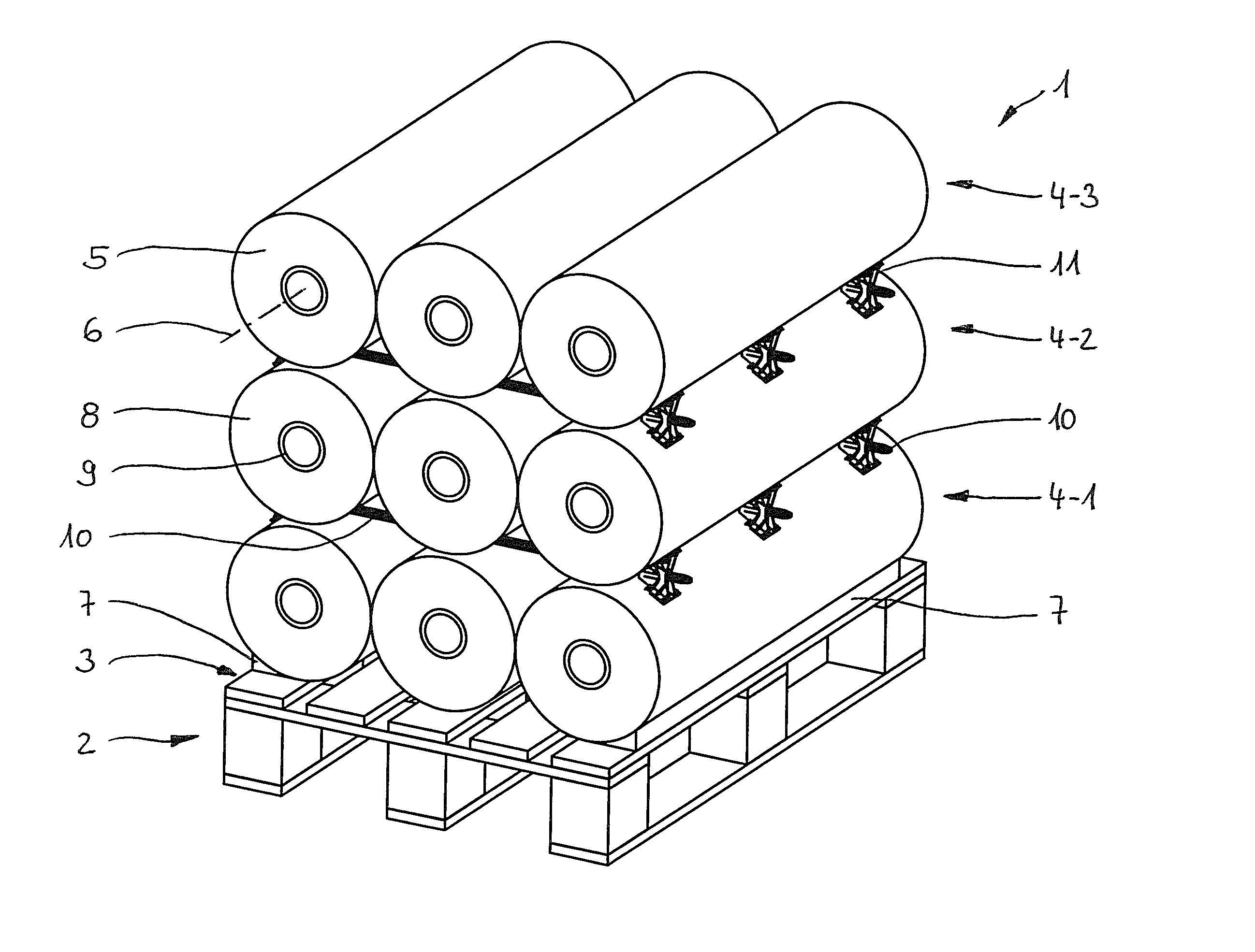
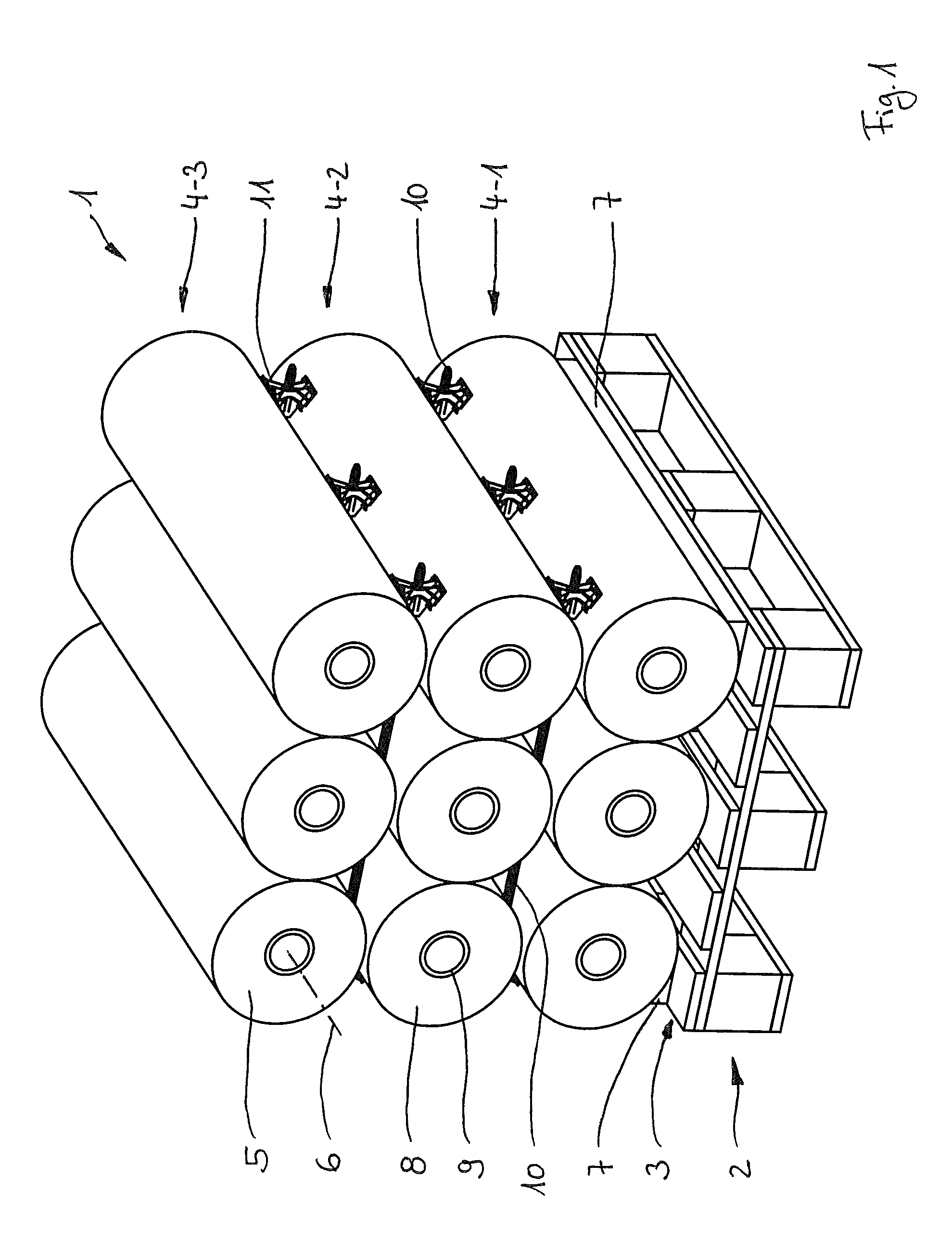
[0044]FIG. 1 illustrates a transport unit 1 according to the invention in a three dimensional view including a plate shaped transport base 2 configured as a wooden pallet which is used as support surface 3 for three layers 4-1, 4-2, 4-3 of three respective cargo items 5 arranged parallel to one another with horizontally extending center axes 6. In order to secure the lowest layer 4.1 on the pallet the two outer cargo items 5 are respectively secured with an elongated wedge 7 which has approximately the same length as the cargo items 5. The two wedges 7 are made from cardboard and are provided on their top sides with bulges that correspond to the cargo items 5.

[0045]These cargo items 5 are coils 8 of a web-shaped foil, wherein the coils are wound onto a sleeve-shaped winding core 9 made from cardboard material. The diameter of the coil 8 is typically between 30 cm and 60 cm, and the length is approximately 4.00 m.

[0046]Cargo items 5 of a layer 4-1, 4-2, 4-3, which are arranged adjace...


PUM


Abstract

A transport unit is provided for cylindrical cargo items supported on a support surface and arranged in parallel in at least two layers. The center axes of cargo items are arranged on top of one another and extend essentially in the same vertical plane. At least one tension device extends between two layers. The tension device extends from an outside edge of a cargo item to an outside edge of an opposing cargo item in the layer. At least two stop elements are positioned on respective ends of the tension device. The stop elements are formed for engaging the cargo items and at least one of the stop elements being adjustably positionable on one end of the tension device. The stop elements being connectable by the tension device in a force transferring manner relative to the cargo items.

Description

FIELD OF THE INVENTION[0001]The present invention relates to a transport unit including:[0002]cylindrical cargo items placed on a support surface, which are arranged parallel to one another and in at least two layers, wherein the horizontally extending center axes respectively have a distance from one another and wherein enveloping surfaces of adjacent cargo items are in a line contact with one another; and[0003]cargo securing devices configured as tension devices, through which the cargo items are secured on the support surface against sliding or rolling in a direction perpendicular to their center axes.[0004]The invention furthermore relates to a set for securing cylindrical cargo items.[0005]Support surfaces in the sense of the present invention are all surfaces on which cargo items can be supported. These are also simple ground surfaces of a storage facility. Preferably, the cargo items are stored on pallets of any type, since they can be moved in a simple manner by a forklift a...

Claims


Application Information

Patent Timeline
Patent Type & Authority Patents(United States)
IPC IPC(8): B60P7/12
CPCB60P7/12B65D19/44B65D67/02B65D71/0096B65D2519/00029B65D2519/00064B65D2519/00099B65D2519/00273B65D2519/00293B65D2519/00298B65D2519/00323B65D2519/00333B65D2519/00815B65D2571/00067
Inventor QUICK, DIETERSUNGER, MARKUSKOHL, HANS GUNTHER
Owner SONOCO DEV INC
Why Eureka
Try Eureka