
Sensorless relative humidity control in a fuel cell application

a technology of relative humidity control and fuel cell, which is applied in the direction of cell components, electrochemical generators, cell component details, etc., can solve the problems of inability to accurately determine the relative humidity of the cathode input airflow, the inability to provide the required accuracy of dew-point sensors in automotive applications, and the relative cost of sensors

Inactive Publication Date: 2013-06-25
GM GLOBAL TECH OPERATIONS LLC
View PDF9 Cites 5 Cited by
  • Summary
  • Abstract
  • Description
  • Claims
  • Application Information

AI Technical Summary

Benefits of technology

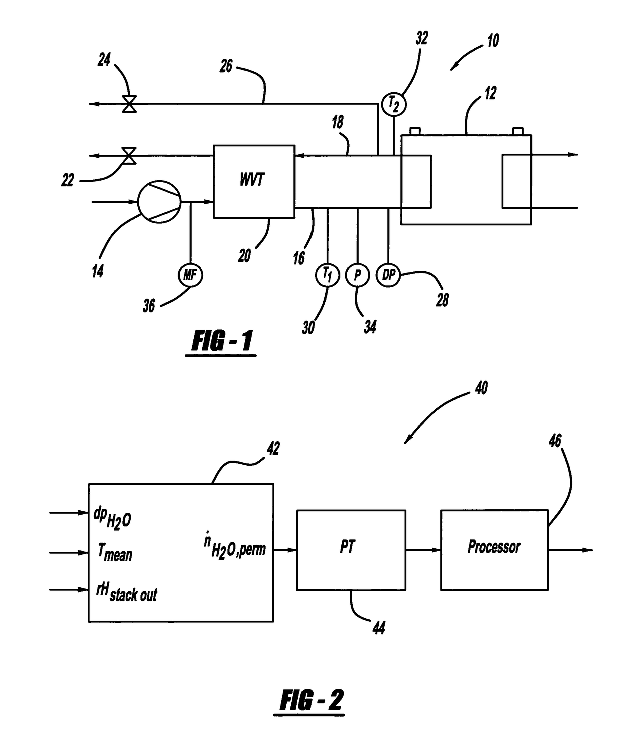
[0013]In accordance with the teachings of the present invention, a technique for determining the relative humidity of the cathode input airflow to a fuel cell stack is disclosed that eliminates the need for a dew-point sensor. The cathode input airflow is humidified by a water vapor transfer unit that uses water in the cathode exhaust gas. The technique employs an algorithm that determines the flow of water into the cathode inlet of the stack. In one embodiment, the algorithm determines the volume flow of water through the water vapor transfer unit using the Arrhenius equation, and then converts the water volume flow to a water mole flow. The algorithm then uses the water mole flow through the water vapor transfer unit and the water mole flow of ambient air to determine the water mole flow into the cathode inlet. The algorithm then uses the water mole flow into the cathode inlet to determine the relative humidity of the cathode air flow.

Problems solved by technology

However, the known dew-point sensors used for this purpose have a number of disadvantages that affect the ability to accurately determine the relative humidity of the cathode input airflow.
Particularly, dew-point sensors that provide the required accuracy are not standard in automotive applications.
Further, these sensors are relatively expensive, have low reliability and require analog control inputs.
Also, the known dew-point sensors have problems with transient behavior and do not provide accurate readings if a droplet of water forms on the sensor contacts.

Method used


Image

  • Sensorless relative humidity control in a fuel cell application

Examples


Embodiment Construction

[0017]The following discussion of the embodiments of the invention directed to a technique for modeling a water vapor trap unit in a fuel cell system to determine the relative humidity of a cathode input airflow is merely exemplary in nature, and is in no way intended to limit the invention or its applications or uses.

[0018]According to the present invention, a method for estimating the transferred flow of the water through the WVT unit 20 is disclosed that can be used to determine the relative humidity of the cathode input airflow to the stack 12 on the line 16. From the transferred water flow estimation, the temperature of the airflow, the pressure in the input line 16 and the position of the control valves 22 and 24, the relative humidity of the cathode input airflow can be calculated. By adding the product water mass flow to the cathode airflow, the estimation of the stack outlet relative humidity can be determined by knowing the temperature and pressure. The flow distribution o...


PUM

PropertyMeasurementUnit
relative humidityaaaaaaaaaa
volume flowaaaaaaaaaa
activation energyaaaaaaaaaa

Abstract

A technique for determining the relative humidity of the cathode input airflow to a fuel cell stack that eliminates the need for a dew-point sensor. The cathode input airflow is humidified by a water vapor transfer unit that uses water in the cathode exhaust gas. The technique employs an algorithm that determines the flow of water into the cathode inlet of the stack. In one embodiment, the algorithm determines the volume flow of water through the water vapor transfer unit using the Arrhenius equation, and then converts the water volume flow to a water mole flow. The algorithm then uses the water mole flow through the water vapor transfer unit and the water mole flow of ambient air to determine the water mole flow into the cathode inlet. The algorithm then uses the water mole flow into the cathode inlet to determine the relative humidity of the cathode airflow.

Description

BACKGROUND OF THE INVENTION[0001]1. Field of the Invention[0002]This invention relates generally to a technique for determining the relative humidity of a cathode input airflow to a fuel cell stack and, more particularly, to a technique for determining the relative humidity of a cathode input airflow to a fuel cell stack that includes determining water flow through a water vapor trap unit that humidities the cathode input airflow.[0003]2. Discussion of the Related Art[0004]Hydrogen is a very attractive fuel because it is clean and can be used to efficiently produce electricity in a fuel cell. A hydrogen fuel cell is an electro-chemical device that includes an anode and a cathode with an electrolyte therebetween. The anode receives hydrogen gas and the cathode receives oxygen or air. The hydrogen gas is dissociated in the anode to generate free protons and electrons. The protons pass through the electrolyte to the cathode. The protons react with the oxygen and the electrons in the ca...

Claims


Application Information

Patent Timeline
Patent Type & Authority Patents(United States)
IPC IPC(8): H01M8/06
CPCH01M8/04141H01M8/04291H01M8/04335H01M8/0435H01M8/04395H01M8/04507H01M8/04753H01M8/04835H01M2008/1095Y02E60/50
Inventor BECKER, MARCMAIER, OLIVERWILLIMOWSKI, PETER
Owner GM GLOBAL TECH OPERATIONS LLC
Learn More