
Communication system, information analyzing apparatus and information analyzing method

a technology of information analysis and communication system, applied in the field of communication system, information analysis apparatus and information analysis method, can solve the problems of imposing burdens and taking time to obtain survey results, and achieve the effect of easy and quick, easy and quick to obtain survey results

Active Publication Date: 2013-06-18
NTT DOCOMO INC
View PDF5 Cites 0 Cited by
  • Summary
  • Abstract
  • Description
  • Claims
  • Application Information

AI Technical Summary

Benefits of technology

Enables the rapid and accurate collection of macroscopic population distribution data and survey results in almost real-time, improving efficiency and reducing the burden on surveyed individuals.

Problems solved by technology

This survey requires a series of very laborious activities such as distributing questionnaires to those surveyed, collecting them, and tallying them with many workers, whereby it takes time to obtain the survey results.
On those surveyed who respond, this survey also imposes burdens such as filling out and sending the questionnaires.

Method used


Image

  • Communication system, information analyzing apparatus and information analyzing method
  • Communication system, information analyzing apparatus and information analyzing method
  • Communication system, information analyzing apparatus and information analyzing method

Examples


first embodiment

[0031][Structure of Communication System]

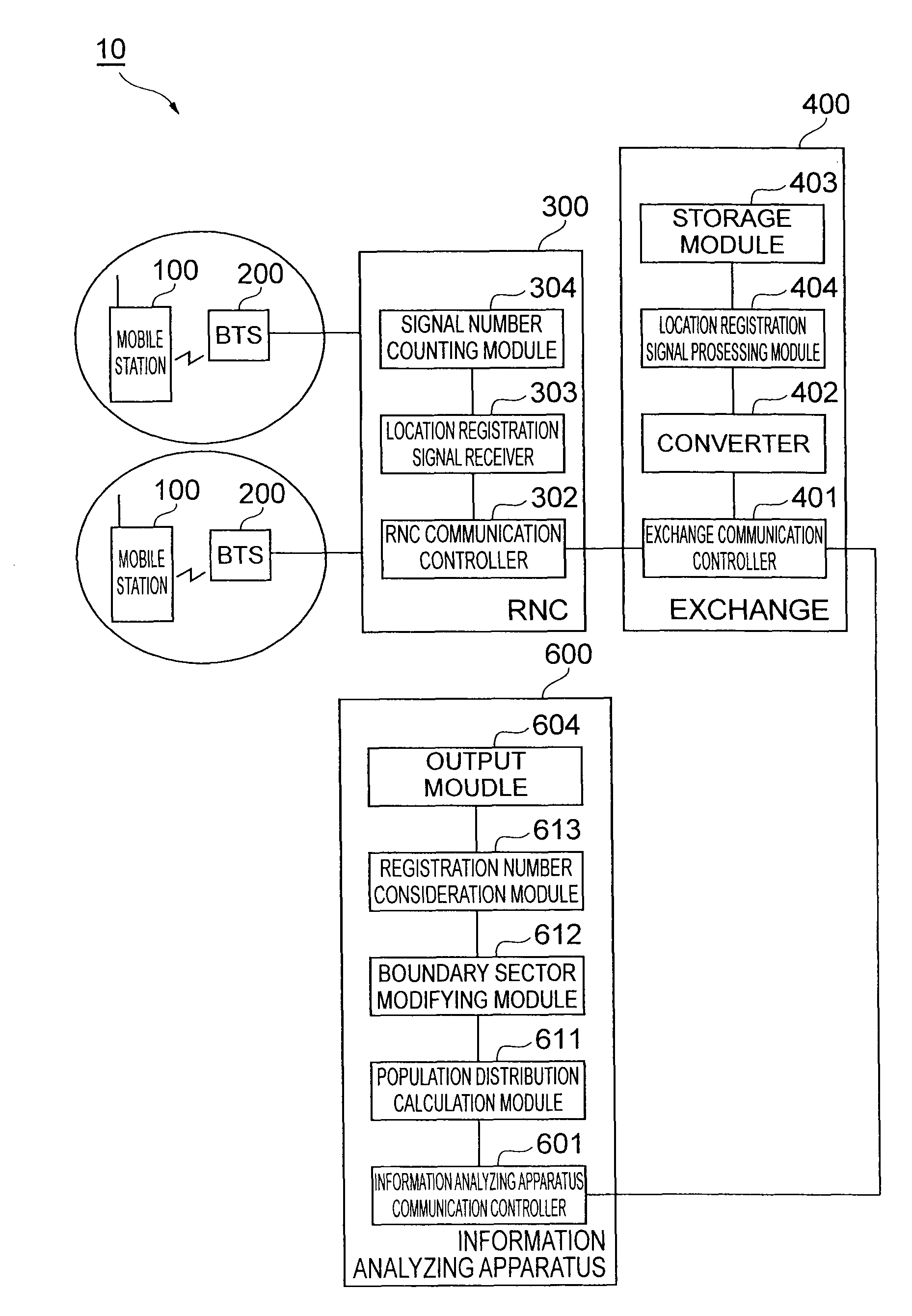
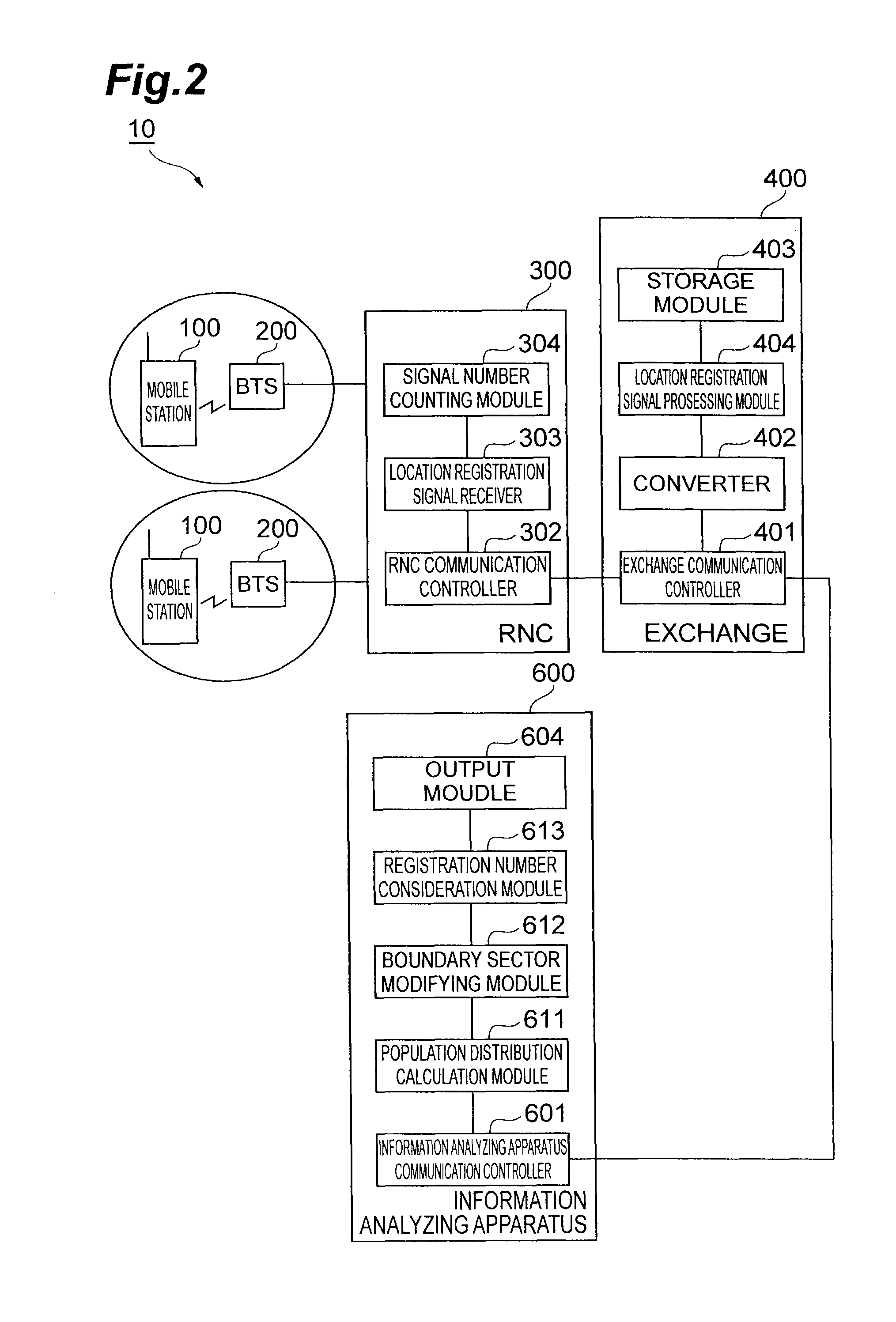
[0032]FIG. 1 is a diagram illustrating a system structure of a communication system 10 according to an embodiment of the present invention. As illustrated in FIG. 1, the communication system 10 is configured to include mobile stations 100, base transceiver stations (BTSs) 200, radio network controllers (RNCs) 300, exchanges 400, and a management center 500. The management center 500 is configured to include social sensor units 501, peta-mining units 502, mobile demography units 503, and visualization solution units 504.

[0033]The RNC 300 receives location registration signals that the mobile stations 100 transmit via the BTS 200, and counts the number of the location registration signals. It should be noted that in the standardized specification “Radio Resource Control (RRC) Protocol Specification: 3GPP TS 25.331”, counting the number of location registration signals by sectors performed by the RNC 300 is specified, and thus the present method...

second embodiment

[0109]FIG. 12 is a system structure diagram of a communication system 10a according to a second embodiment of the present invention. As illustrated in FIG. 12, this communication system 10a has a system structure for the case of applying it to Long Term Evolution (LTE) that is a new communication standard, and is configured to include mobile stations 100, Evolution Node Bs (eNBs) 250, exchanges 400, and a management center 500. The management center 500 is configured with social sensor units 501, peta-mining units 502, mobile demography units 503, and visualization solution units 504. The eNB 250 includes both functions of the BTS 200 and the RNC 300.

[0110]The second embodiment is a system structure for the case of applying it to LTE and the contents of its specific processes are the same as those of the above-mentioned first embodiment, and accordingly its specific description is omitted. In the first embodiment, its protocol is Radio Access Network Application Part (RANAP). In the...


PUM


Abstract

For easily and quickly collecting data regarding macroscopic population distribution, and easily and quickly obtaining the survey results, an RNC includes: a location registration signal receiver that receives location registration signals, and a signal number counting module that counts the number of the location registration signals for each sector, and an information analyzing apparatus includes: a population distribution calculation module that calculates population distribution information based on the number of the location registration signals; and an output module that outputs the population distribution information.

Description

TECHNICAL FIELD[0001]The present invention relates to an information analyzing apparatus and an information analyzing method for performing an approximation of population distribution and a communication system that is configured to include the information analyzing apparatus.BACKGROUND ART[0002]Conventionally, as a method of collecting data regarding macroscopic population distribution, there is a census that is conducted on a 5-year cycle. This survey requires a series of very laborious activities such as distributing questionnaires to those surveyed, collecting them, and tallying them with many workers, whereby it takes time to obtain the survey results. On those surveyed who respond, this survey also imposes burdens such as filling out and sending the questionnaires.CITATION LISTPatent Literature[0003][Patent Literature 1] Japanese Patent Application Laid-Open Publication No. 2003-44969SUMMARY OF INVENTIONTechnical Problem[0004]As described above, conventionally, even only colle...

Claims


Application Information

Patent Timeline
Patent Type & Authority Patents(United States)
IPC IPC(8): H04H60/66G06Q30/00
CPCG06Q30/00H04W60/00H04W24/00H04W88/08H04W88/12
Inventor SUZUKI, TOSHIHIROOKAJIMA, ICHIROKAWAKAMI, HIROSHIJO, MANHEEOCHI, DAISUKENAGATA, TOMOHIROKOBAYASHI, MOTONARIOYABU, YUKI
Owner NTT DOCOMO INC
Learn More