
Low profile mobile tri-band antenna system

a tri-band antenna and low-profile technology, applied in the direction of independent non-interfering antenna combinations, broadcasting with distribution, transmission, etc., can solve the problems of phased array antenna systems that cannot meet the multi-band requirements of mechanical antenna systems, limited range of phased array antenna systems, and high frequency, etc., to achieve low cost, high gain characteristic, and effective forming

Inactive Publication Date: 2013-06-11
ELECTRONICS & TELECOMM RES INST
View PDF9 Cites 3 Cited by
  • Summary
  • Abstract
  • Description
  • Claims
  • Application Information

AI Technical Summary

Benefits of technology

The present invention is a mobile tri-band antenna system that has the following technical effects: it can provide Ku satellite broadcasting and Ka / K satellite communication multimedia services, it is mobile-mountable and has a multi-band and high-gain characteristic at a low cost, it can effectively receive satellite signals from geo-stationary satellites, it can track a target satellite at high speed, and it can operate using a quasi-monopulse operation to direct the target satellite.

Problems solved by technology

The mechanical antenna system becomes incapable of tracking a satellite when the antenna beam becomes narrower, for example, narrower than 1.0°, due to the increment of a gain.
Also, a phased array antenna system satisfying a multi-band, a high frequency, a high gain, and a wide beam scan sector is very expensive, and such a phased array antenna system has limitations to embody.

Method used


Image

  • Low profile mobile tri-band antenna system
  • Low profile mobile tri-band antenna system
  • Low profile mobile tri-band antenna system

Examples


Embodiment Construction

[0030]Other objects and aspects of the invention will become apparent from the following description of the embodiments with reference to the accompanying drawings, which is set forth hereinafter.

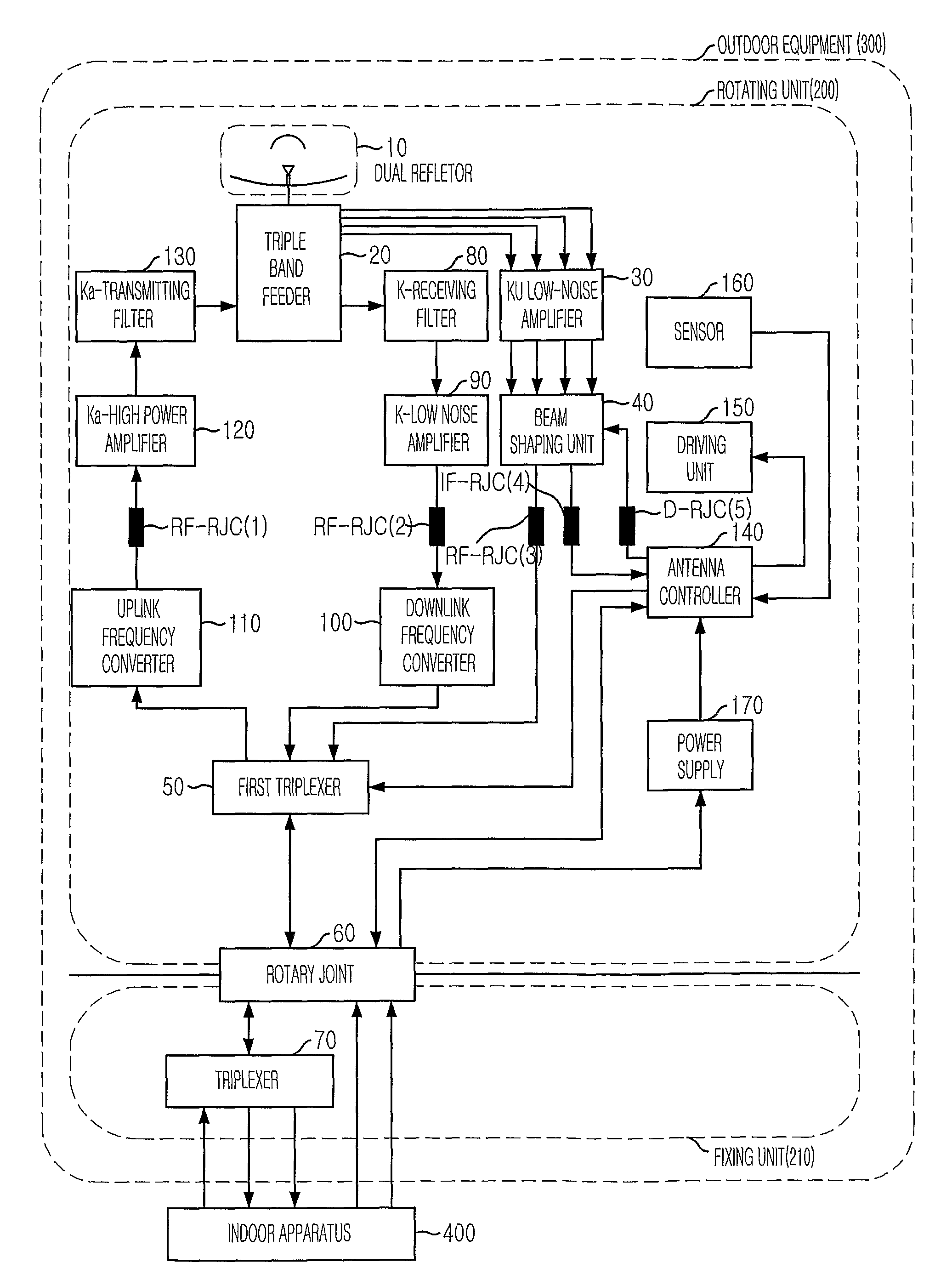
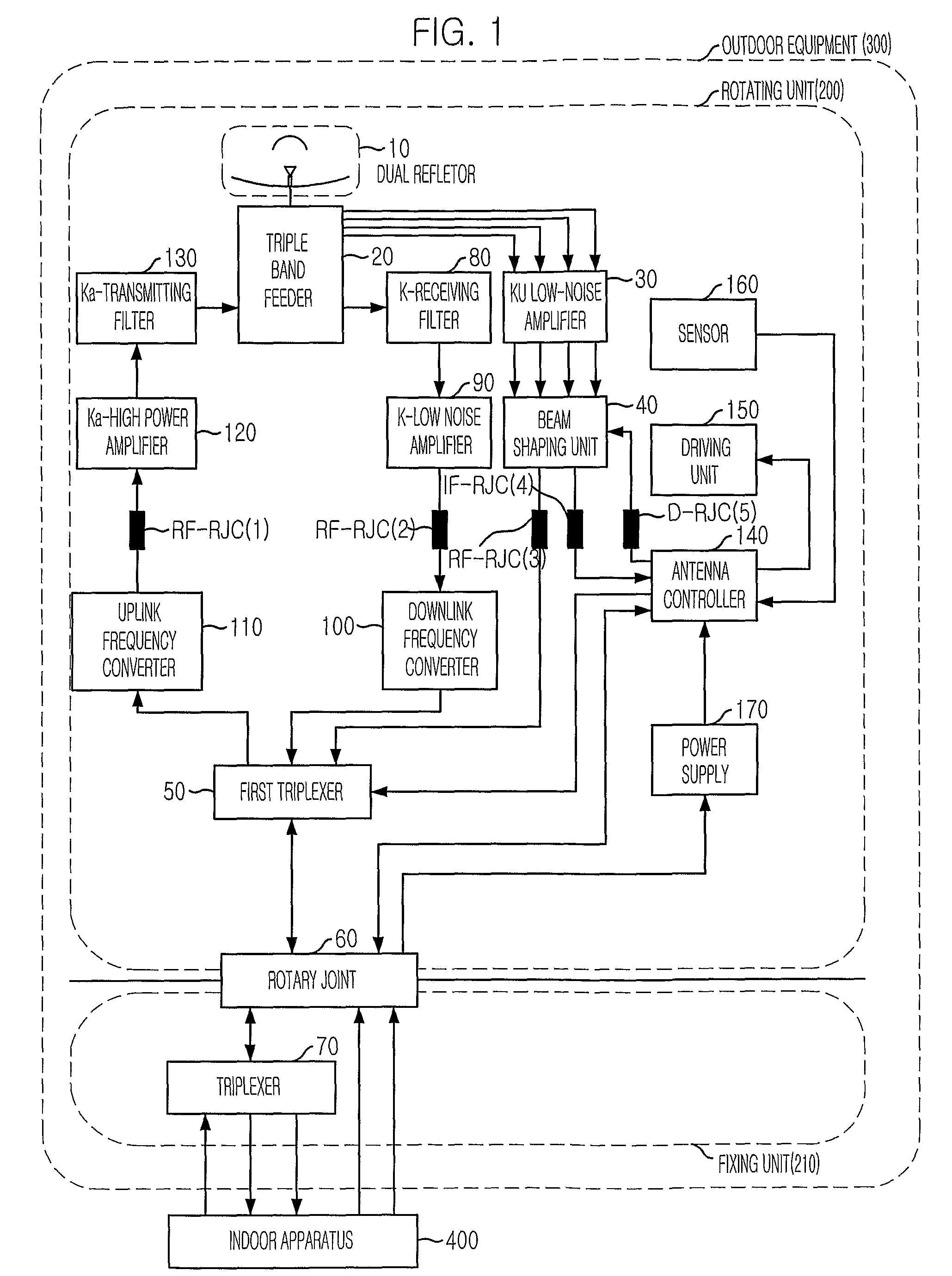
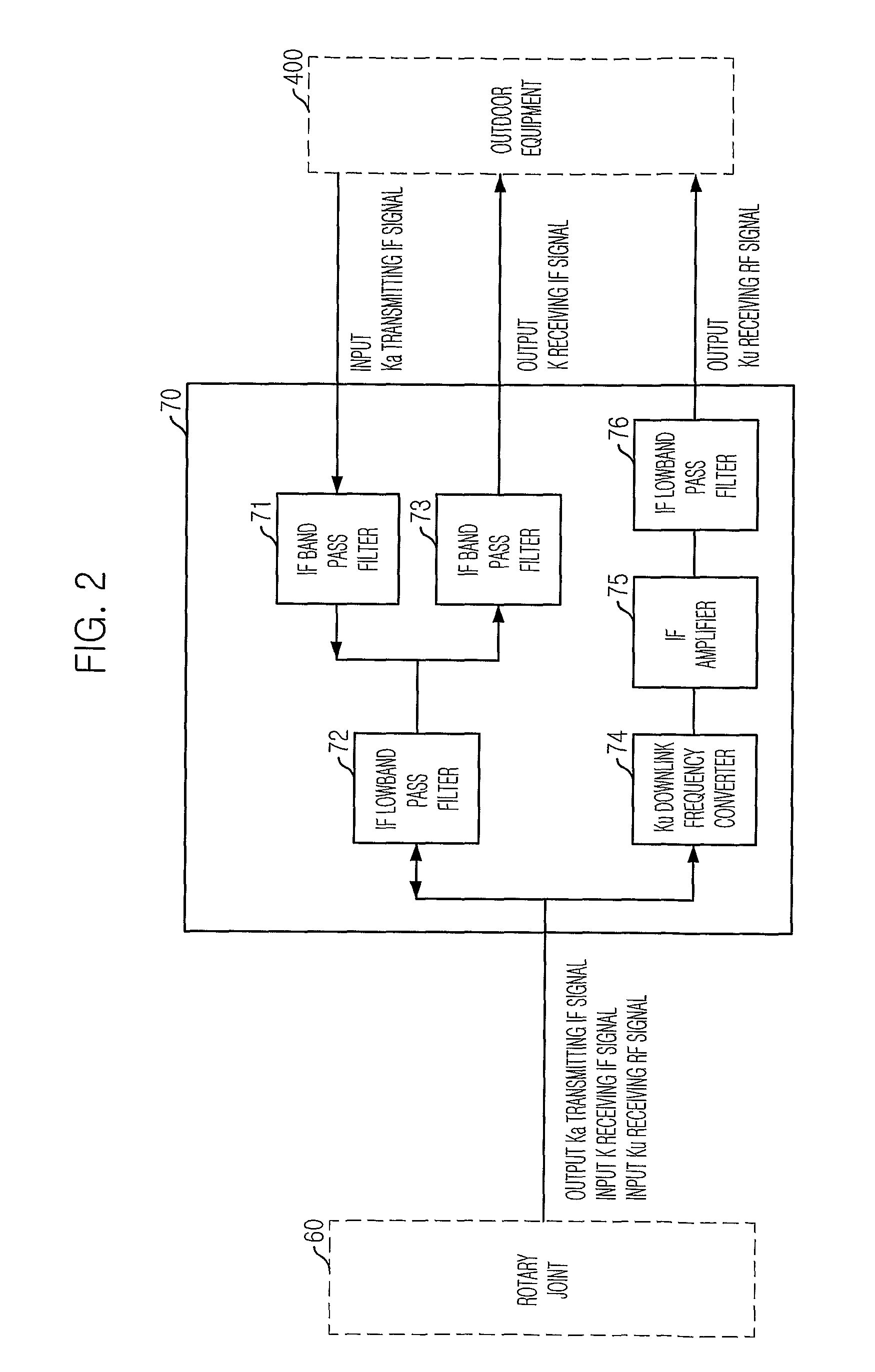
[0031]An antenna system according to the present invention uses a tri-band service satellite that provides a communication and broadcasting signal. That is, the tri-band signal includes a Ka transmitting signal that denotes a k-band satellite communication transmitting signal, a K receiving signal that denotes a K-band satellite communication receiving signal, and a Ku receiving signal that denotes a Ku-band satellite broadcasting signal.

[0032]FIG. 1 is a block diagram illustrating a mobile tri-band antenna system in accordance with an embodiment of the present invention.

[0033]Referring to FIG. 1, the mobile tri-band antenna system according to the present embodiment is divided into an outdoor apparatus 300 and an indoor apparatus 400.

[0034]The outdoor apparatus 300 includes a rotating unit...


PUM


Abstract

Provided is a mobile tri-band antenna system having low profile. The antenna system includes a tri-band feeding unit for dividing a satellite broadcasting signal by a signal channel in an azimuth angle and an elevation angle, and transmitting / receiving the satellite communication signal through distinguishing the satellite communication signal; a beam shaping unit for dividing the satellite broadcasting signals into a first channel signal and a second channel signal, combined power thereof through channel switching; an antenna controlling unit for driving an antenna system in an azimuth and elevation angle to direct the satellite according to the power combined second channel signal from the beam shaping unit; a first triplexer unit for outputting the power combined first channel signal to a rotary joint unit; a second triplexer unit for converting the first channel signal inputted to a downlink frequency and providing the converted first channel signal to the indoor apparatus.

Description

TECHNICAL FIELD[0001]The present invention relates to a low profile mobile tri-band antenna system for tracking a satellite by driving an antenna system according to an azimuth angle and an elevation angle, which direct the satellite, using a satellite receiving signal.BACKGROUND ART[0002]Generally, an antenna structure for an antenna system is selected depending on a performance, a cost, and an environment thereof. That is, the antenna structure must be selected in order to develop a low cost antenna that satisfies a high gain antenna characteristic in a high frequency band and a multi-band which are a communication environment between a satellite and a mobile object.[0003]A conventional antenna system includes a mechanical antenna system and a phased array antenna system.[0004]The mechanical antenna system is mainly used for long distance satellite communication for providing a fixed antenna beam. Especially, the mechanical antenna system is widely used as a low gain single or dua...

Claims


Application Information

Patent Timeline
Patent Type & Authority Patents(United States)
IPC IPC(8): H04B7/185
CPCH01Q1/3275H01Q3/04H01Q5/55H01Q21/28H01Q25/007H01Q19/19H01Q1/27
Inventor EOM, SOON-YOUNGJUNG, YOUNG-BAESON, SEONG-HOYUN, JAE-SEUNGJEON, SOON-IK
Owner ELECTRONICS & TELECOMM RES INST
Learn More