
Jacking system

a jacking system and jacking technology, applied in the field of jacking systems, can solve the problems of high load handling, compactness or complexity, jacking speed, holding efficiency, etc., and achieve the effects of easy and cheap construction, and reducing the length of the legs of the jacking system

Active Publication Date: 2013-06-11
GUSTOMSC RESOURCES BV
View PDF13 Cites 4 Cited by
  • Summary
  • Abstract
  • Description
  • Claims
  • Application Information

AI Technical Summary

Benefits of technology

The system reduces leg length, enhances jacking speed, provides stability, and allows for efficient handling of large loads, enabling faster and more controlled operations, including pre-loading and leg retrieval, while maintaining horizontal platform position during phases like jacking and lowering.

Problems solved by technology

Handling of high loads may be a problem, as well is simultaneously handling several legs on one platform.
All these systems thus have several disadvantages regarding jacking speed, holding efficiency, compactness or complexity.
Others need relatively high frames or lack stability.

Method used


Image

  • Jacking system
  • Jacking system
  • Jacking system

Examples


Embodiment Construction

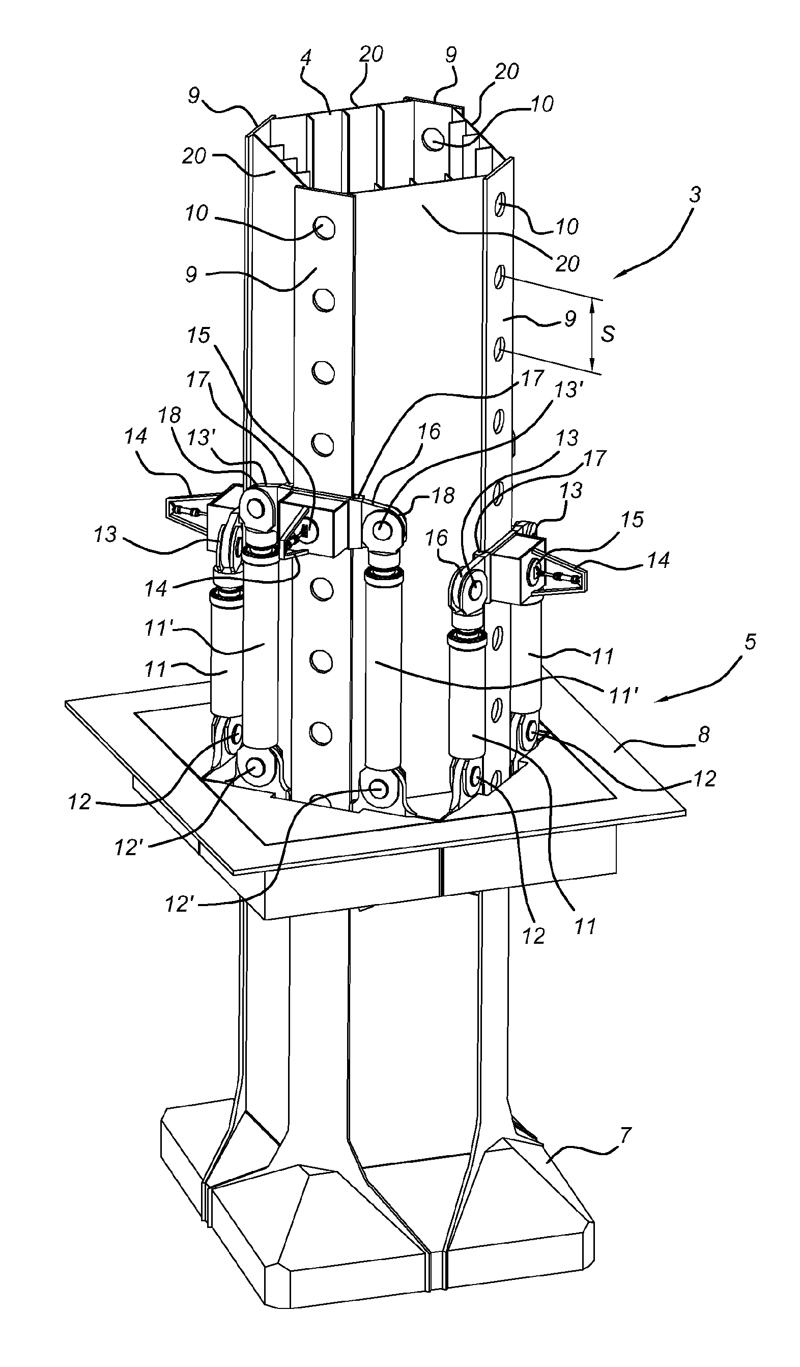
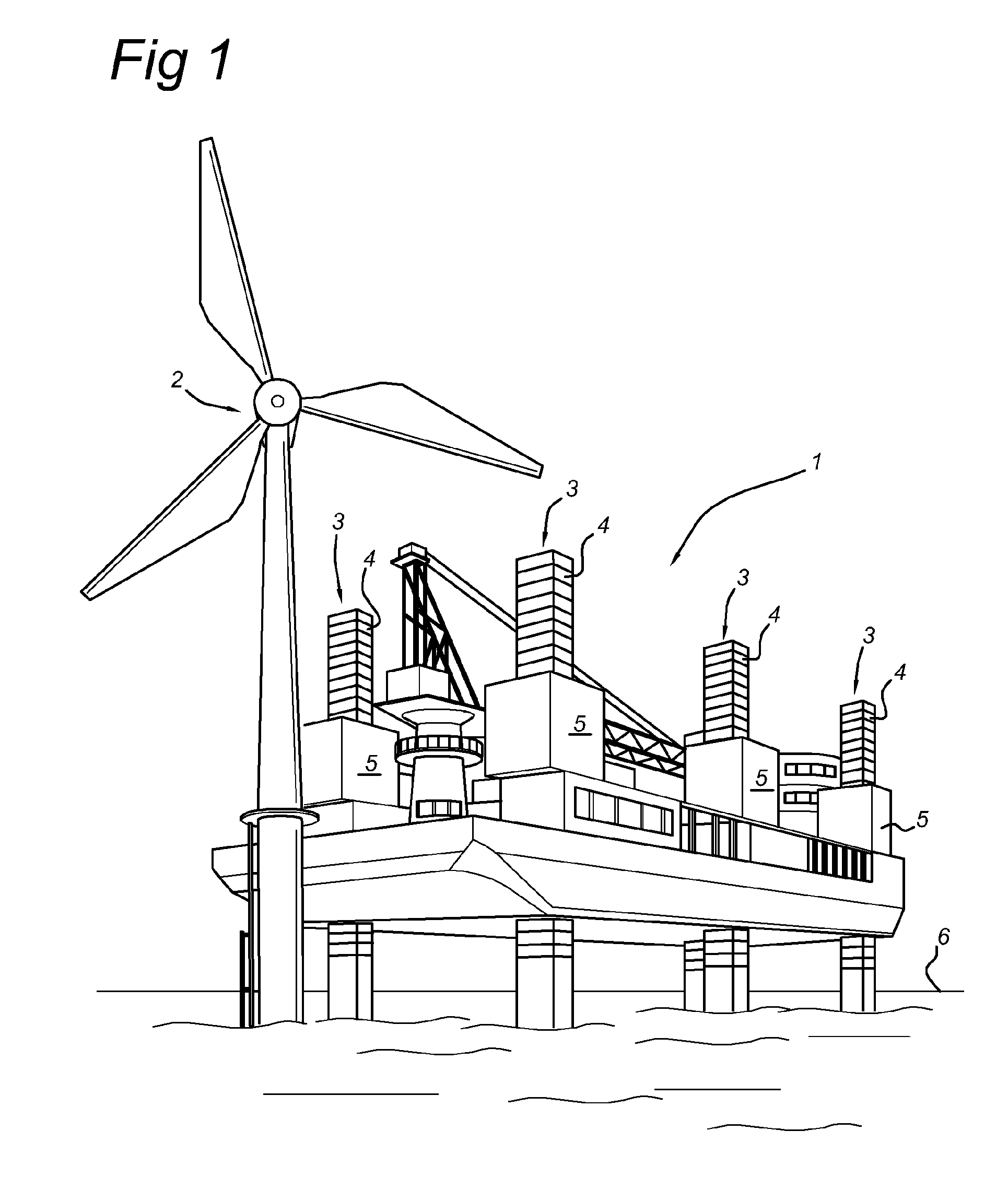
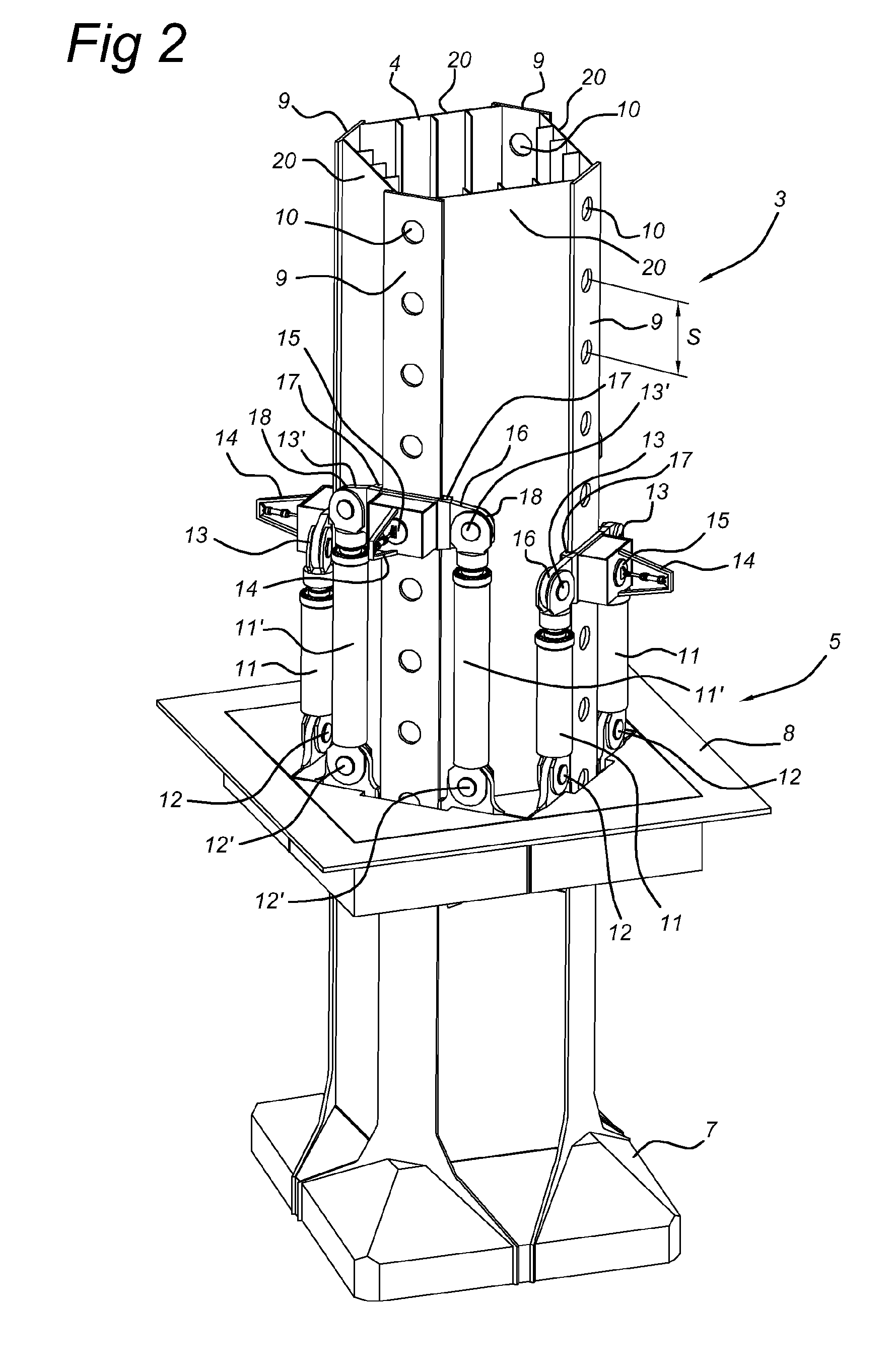
[0059]In FIG. 1 a vessel 1 is shown for placing offshore constructions such as a windmill 2. The vessel is provided with a number of jacking systems 3 for jacking or lifting the vessel out of the water, i.e. above the surface of the water. To that end, the legs 4 rest on the bottom of the sea.

[0060]For installing for instance a windmill, the vessel 1 has the windmill 2 on board and sails to a location where the windmill has to be placed. At that location, the legs 4 of the vessel are lowered until they rest on the seafloor. This stage is called leg handling phase. Then, the vessel is lifted out of the water using the guiding frames 5 which engage the legs 4. This stage is called the jacking phase. After the vessel is lifted out of the water, the windmill is erected and placed on the seafloor. After installation of the windmill, the vessel is lowered again, and subsequently the legs 4 are raised from the seafloor using the guiding frames 5, and the vessel sails away. It is clear that...


PUM


Abstract

A jacking system for jacking a structure, includes a leg having a longitudinal axis and including first engagement parts along the leg, and a guiding frame displaceable along the leg. The guiding frame includes at least a first, second, third and fourth actuator, the actuators each having a first and second actuator part which in operation can displace with respect to one another along the leg, the first actuator part of the actuators coupled to the guiding frame, the second actuator parts of the actuators each coupled to first engagement parts for engaging and disengaging the first engagement parts of the leg for providing abutment in the longitudinal direction of the leg, the second actuator parts of the actuators displaceable along the leg past one another, and the actuators being arranged in pairs opposite one another with respect to a longitudinal plane of the leg.

Description

BACKGROUND[0001]The present invention relates to a jacking system for jacking a structure, for instance offshore platforms or vessels, out of the water, and a method for jacking using this system.[0002]Such a jacking system is for instance disclosed in U.S. Pat. No. 3,804,369. This jacking system has pairs of hydraulic cylinders which are mutually coupled using wire cables.[0003]Another such jacking system is disclosed in U.S. Pat. No. 4,007,914. This system has three mutually fixed frame parts. One end of a hydraulic cylinder is fixed to one frame part, one end of another hydraulic cylinder is fixed to a next frame. The other ends of the hydraulic cylinders are coupled.[0004]Yet another such jacking system is disclosed in U.S. Pat. No. 4,411,408. This jacking system has a leg which has several “chords” each having two hydraulic cylinders at opposite sides of a chord. Both ends of the hydraulic cylinders have a retractable pin which can be extended into passages in a chord. Both cyl...

Claims


Application Information

Patent Timeline
Patent Type & Authority Patents(United States)
IPC IPC(8): E02B17/08
CPCE02B17/0809E02B17/0872E02B2017/0091
Inventor VAN NOOD, CORNELIS PIETER AARTDRIANUSCOMMANDEUR, JOHAN ALBERTHOFMAN, JOHANNES ANDRIES
Owner GUSTOMSC RESOURCES BV
Learn More