
Methods and apparatus for assembling and operating electronic device manufacturing systems

a manufacturing system and electronic device technology, applied in the direction of machine/engine, process and machine control, program control, etc., can solve the problems of increasing the amount of time required for shipping an electronic device manufacturing system, and affecting the quality of electronic devices

Inactive Publication Date: 2013-06-04
APPLIED MATERIALS INC
View PDF67 Cites 20 Cited by
  • Summary
  • Abstract
  • Description
  • Claims
  • Application Information

AI Technical Summary

Benefits of technology

The patent text describes a method and system for manufacturing electronic devices. The system includes a process tool and an abatement tool, which work together to produce effluent as a byproduct. The effluent is then abated using an abatement resource. The system also includes a supply of abatement resource, which can be changed from one supply to another without interrupting the flow of abatement resource. This allows for continuous operation of the process tool while using a different abatement resource supply. Additionally, the patent describes a method of stocking and identifying performance requirements for the manufacturing system, selecting components to meet those requirements, and constructing the system with the selected components. The invention has technical benefits in improving the efficiency and effectiveness of electronic device manufacturing processes.

Problems solved by technology

Electronic device manufacturing systems, such as process tools and abatement tools, etc., may be complex assemblies of subsystems or components, and each component may itself be a complex system.
Typically, assembly of an electronic device manufacturing system may take a significant amount of time.
The certification process adds to the amount of time required to ship an electronic device manufacturing system.
When a system is out of service due to the maintenance requirements of a component of the system or of a supporting sub-system, the manufacturer may have to forego significant revenues due to product which is not being manufactured while the system is out of service.

Method used


Image

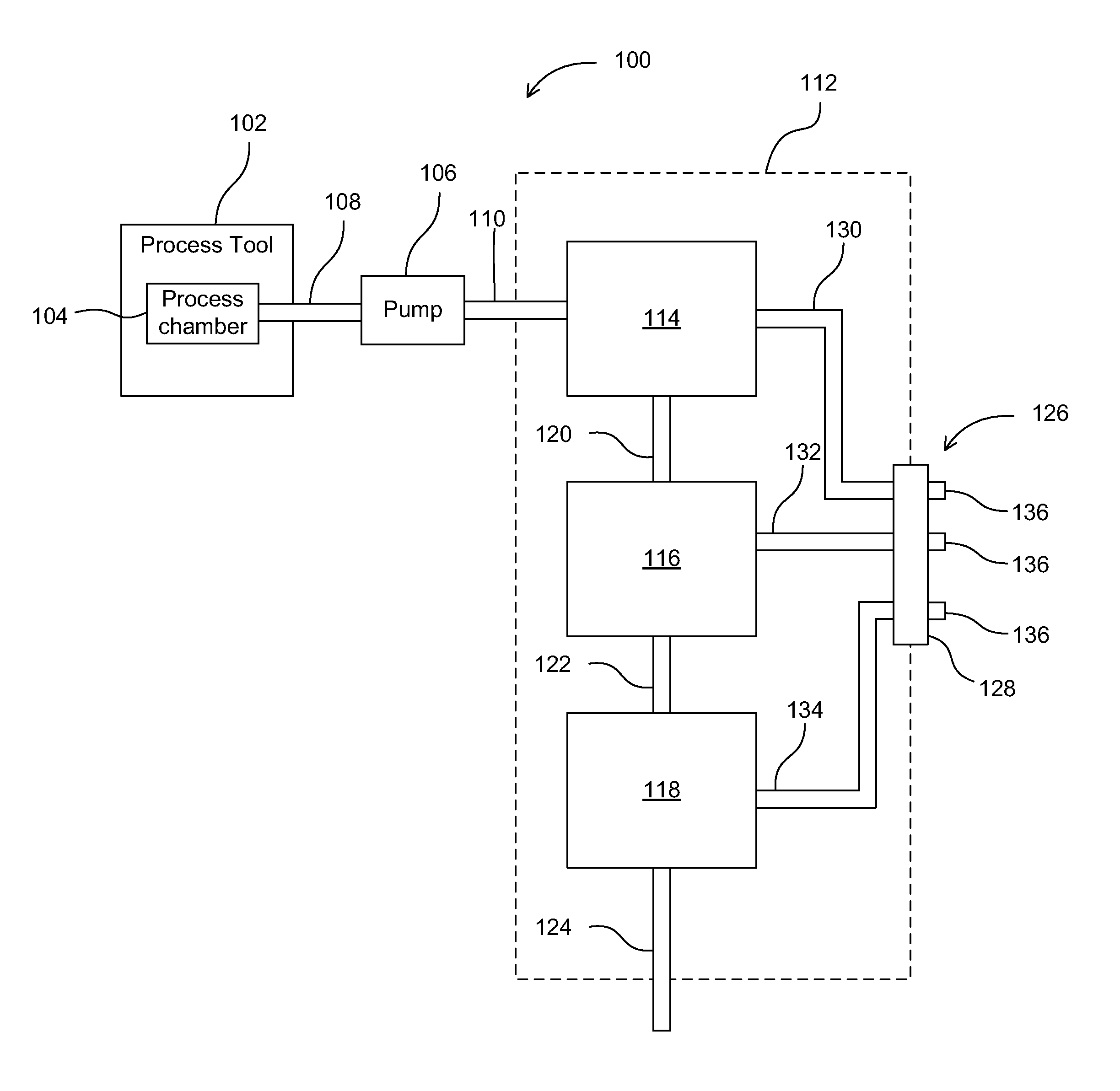
  • Methods and apparatus for assembling and operating electronic device manufacturing systems
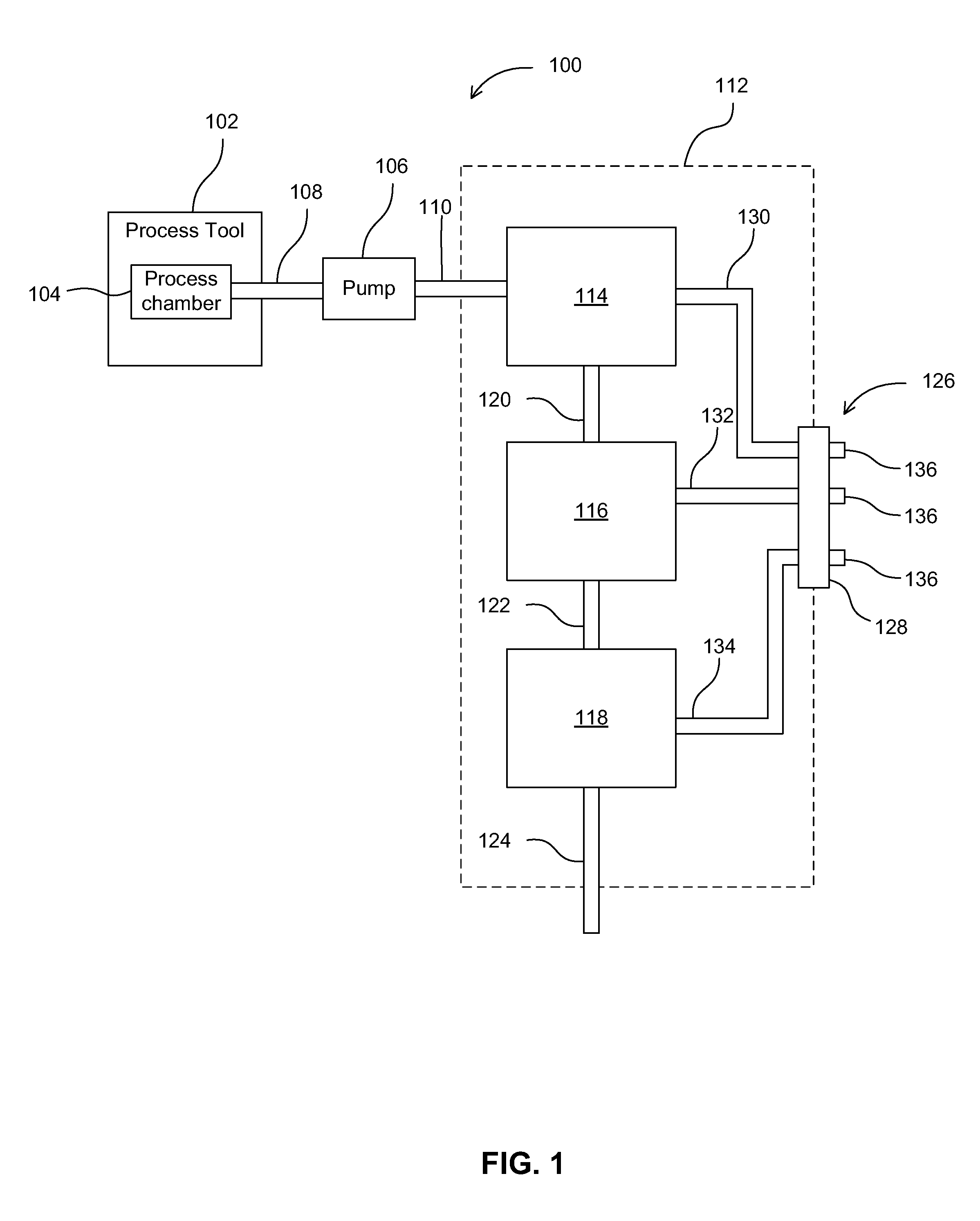
  • Methods and apparatus for assembling and operating electronic device manufacturing systems
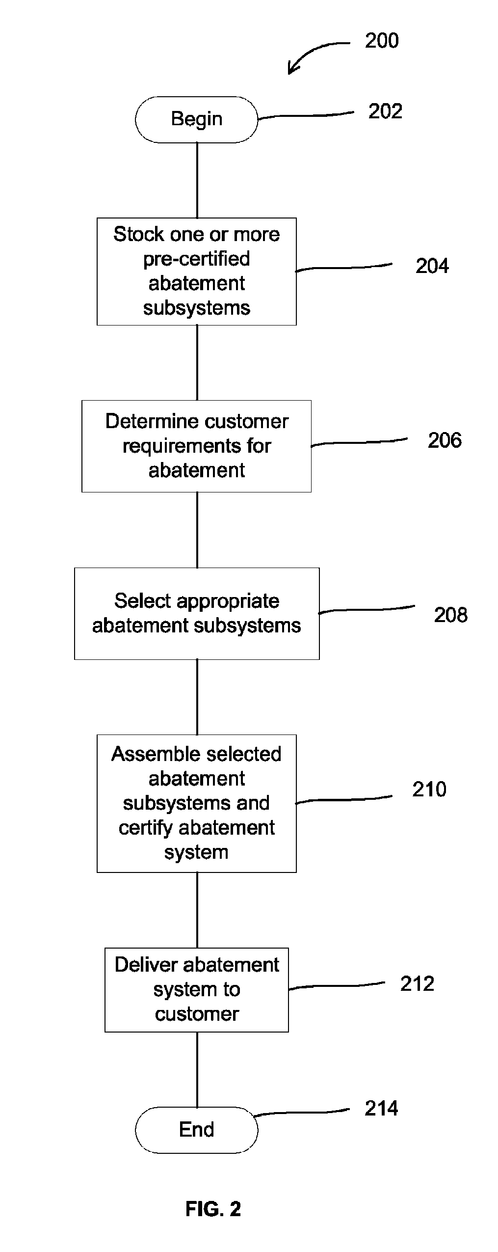
  • Methods and apparatus for assembling and operating electronic device manufacturing systems

Examples


second embodiment

[0033]FIG. 3 is a schematic drawing of an electronic device manufacturing system 300 of the present invention. System 300 may include a process tool 302 which may be connected through conduit 304 to vacuum pump 306. Vacuum pump 306 may, in turn, be connected through conduit 308 to abatement tool 310. Abatement tool 310 may be in fluid connection with abatement resource supply 312 through conduit 314, valve assembly 316, and conduit 318. Valve assembly 316 may include two shut off valves, 320, 322 which may be connected by connector 324. This valve design may enable an operator to prevent the flow of fluids from the abatement resource supply 312 through conduit 314 and also prevent any back flow of fluids from the abatement tool 310 through conduit 318. The connector 324 may enable the operator to disconnect the abatement resource supply 312 from the system 300. Any suitable valve assembly may be utilized.

[0034]System 300 may also include an backup abatement resource supply 326, whic...

third embodiment

[0041]FIG. 5 is a schematic drawing of an electronic device manufacturing system 500 of the present invention. System 500 may include process tools 502, 502a. Process tools 502, 502a may be connected to abatement tools 504, 504a, respectively, by conduits 506, 506a, respectively. Abatement resource supplies 508, 508a may be primary abatement resource supplies to abatement tools 504, 504a, respectively. In some embodiments, abatement resource supply 508 may supply the abatement resource to the abatement tool 504 through primary conduit 510. Similarly, abatement resource supply 508a may supply the same abatement resource to abatement tool 504a through primary conduit 510a.

[0042]Secondary conduit 512 may connect to abatement resource supply 508 to abatement tool 504a. Likewise, secondary conduit 512a may connect abatement resource supply 508a to abatement tool 504.

[0043]Each of the primary conduits 510, 510a and secondary conduits 512, 512a may contain valve assemblies 514, 514a and 5...

fourth embodiment

[0052]FIG. 7 is a schematic drawing of an electronic device manufacturing system 700 of the present invention. System 700 may include process tools 702, 702a which may be connected to abatement tools 704, 704a by conduits 706, 706a. In some embodiments, for any particular abatement resource, each abatement tool may have a primary abatement resource supply for that abatement resource. In FIG. 7, for example, abatement tool 704 may receive an abatement resource from abatement resource supply 708 through conduit 710, valve assembly 712, and valve 714. Likewise, abatement tool 704a may receive the abatement resource from abatement resource supply 708a through conduit 710a valve assembly 712a and valve 714a. Resource supply 708b may be configured as a backup abatement resource supply, and may be connected to both abatement tools 704 and 704a through conduits 716 and 716a respectively.

[0053]In operation, process tools and 702, 702a may produce effluent which may flow through conduits 706,...


PUM

PropertyMeasurementUnit
timeaaaaaaaaaa
flammableaaaaaaaaaa
period of timeaaaaaaaaaa

Abstract

A method for operating one or more electronic device manufacturing systems is provided, including the steps 1) performing a series of electronic device manufacturing process steps with a process tool, wherein the process tool produces effluent as a byproduct of performing the series of process steps; 2) abating the effluent with an abatement tool; 3) supplying an abatement resource to the abatement tool from a first abatement resource supply; 4) changing an abatement resource supply from the first abatement resource supply to a second abatement resource supply, wherein changing the abatement resource supply comprises: i) interrupting a flow of the abatement resource from the first abatement resource supply; and ii) beginning a flow of the abatement resource from the second abatement resource supply; and 5) continuing to perform the series of process steps with the process tool, while changing, and after changing, the abatement resource supply.

Description

[0001]The present application claims priority to U.S. Provisional Patent Application Ser. No. 60 / 931,731, filed May 25, 2007 and entitled “Methods and Apparatus for Abating Effluent Gases Using Modular Treatment Components”, which is hereby incorporated herein by reference in its entirety for all purposes.[0002]The present application also claims priority to U.S. Provisional Patent Application Ser. No. 61 / 026,432 filed Feb. 5, 2008 and entitled “Abatement Systems”, which is hereby incorporated herein by reference in its entirety for all purposes.FIELD OF THE INVENTION[0003]The present invention relates generally to electronic device manufacturing methods and systems, and is more particularly directed to methods and apparatus for assembling and operating such systems.BACKGROUND OF THE INVENTION[0004]Electronic device manufacturing systems, such as process tools and abatement tools, etc., may be complex assemblies of subsystems or components, and each component may itself be a complex...

Claims


Application Information

Patent Timeline
Patent Type & Authority Patents(United States)
IPC IPC(8): H01L21/00
CPCG05B19/4184G05B2219/31386Y10T29/53048Y10T29/49826G05B2219/45026Y02P90/02
Inventor CHANDLER, PHILCLARK, DANIEL O.VERMEULEN, ROBBERT M.JUNG, JAY J.JOHNSON, ROGER M.LOLDJ, YOUSSEF A.SMITH, JAMES L.
Owner APPLIED MATERIALS INC
Learn More