Rotary union with selectively controlled seal

a selective control and sealing technology, applied in the direction of fluid pressure control, fluid couplings, instruments, etc., can solve the problems of high media pressure, high flow rate, high cost and/or difficult repair or replacement of precision components, and components that are often subject to corrosive environments or damage, so as to prevent undesired media leakage and reduce seal life

Active Publication Date: 2013-06-04
DEUBLIN
View PDF29 Cites 8 Cited by
  • Summary
  • Abstract
  • Description
  • Claims
  • Application Information

AI Technical Summary

Benefits of technology

[0011]In general, various embodiments of rotary unions that can maintain engagement between the seal surfaces to prevent undesired media leakage while allowing the seal surfaces to disengage in conditions that can lead to dry running and reduced seal life without significant additional expense to control seal engagement are disclosed. These rotary unions can maintain engagement between the seal surfaces while an internal vacuum is applied to remove media from the fluid channel, and allow seal contact to be maintained even when the distance between the rotating and non-rotating members varies during operation, as with a machining center drawbar during tool change.
[0012]Further, the disclosed rotary unions allow seal engagement to be controlled manually or selectively by the machine designer or the machine's control program using commonly available piping components, as well as automatically according to the nature of the medium being transferred. Such capability increases the functional flexibility of machines by allowing high-speed rotation of 40,000 rpm, or more, with lubricating media (such as water-based coolants or oil-based aerosols such as “minimum quantity lubrication”), non-lubricating media (such as dry air and inert gases), and without any media present.

Problems solved by technology

Often these applications require relatively high media pressures, flow rates, or high machine tool rotational speeds.
Machines using rotary unions typically include precision components, such as bearings, gears, electrical components, and others, that are expensive and / or difficult to repair or replace during service.
These components are often subject to corrosive environments or to damage if exposed to fluid leaking or venting from the rotary union during operation.
When a rotary union is used with non-lubricating media (such as dry air) or without any media, the engaged seal surfaces experience a “dry running” condition, which causes rapid seal wear due to lack of adequate lubrication.
Extended periods of dry running can cause severe damage to the seal members, thereby requiring expensive and time-consuming replacement of one or both seal members.
For example, rotary unions having seal surfaces that disengage when opposing fluid pressures are present, such as the arrangement disclosed in U.S. Pat. No. 5,538,292, can be complex and expensive to manufacture.
Rotary unions having seal surfaces that disengage automatically in the absence of media, such as the arrangement disclosed in U.S. Pat. No. 4,976,282, are less complex to manufacture and incorporate in a machine, but are prone to engagement of the seal surfaces when non-lubricating media is used.
Seal surfaces with special geometries for non-contacting operation with gases, such as those disclosed in U.S. Pat. Nos. 6,325,380 and 6,726,913, do not provide effective sealing with liquid media.
Similarly, seal surfaces with special geometries to distribute the medium evenly, such as the seal arrangement disclosed in U.S. Pat. No. 6,149,160, offer no advantage when non-lubricating media is used.
Rotary unions that engage the seal surfaces at all times, even with a reduced bias, such as the unions disclosed in U.S. Pat. No. 6,929,099, are prone to damage from dry running at high rotating speeds.
This arrangement can prevent dry running, but also causes spillage of medium remaining in the union when the seal surfaces disengage.
Such spillage, especially in multi-axis machines, cannot always be directed away from surrounding components and can damage sensitive components of the machine.

Method used


Image

  • Rotary union with selectively controlled seal
  • Rotary union with selectively controlled seal
  • Rotary union with selectively controlled seal

Examples


Embodiment Construction

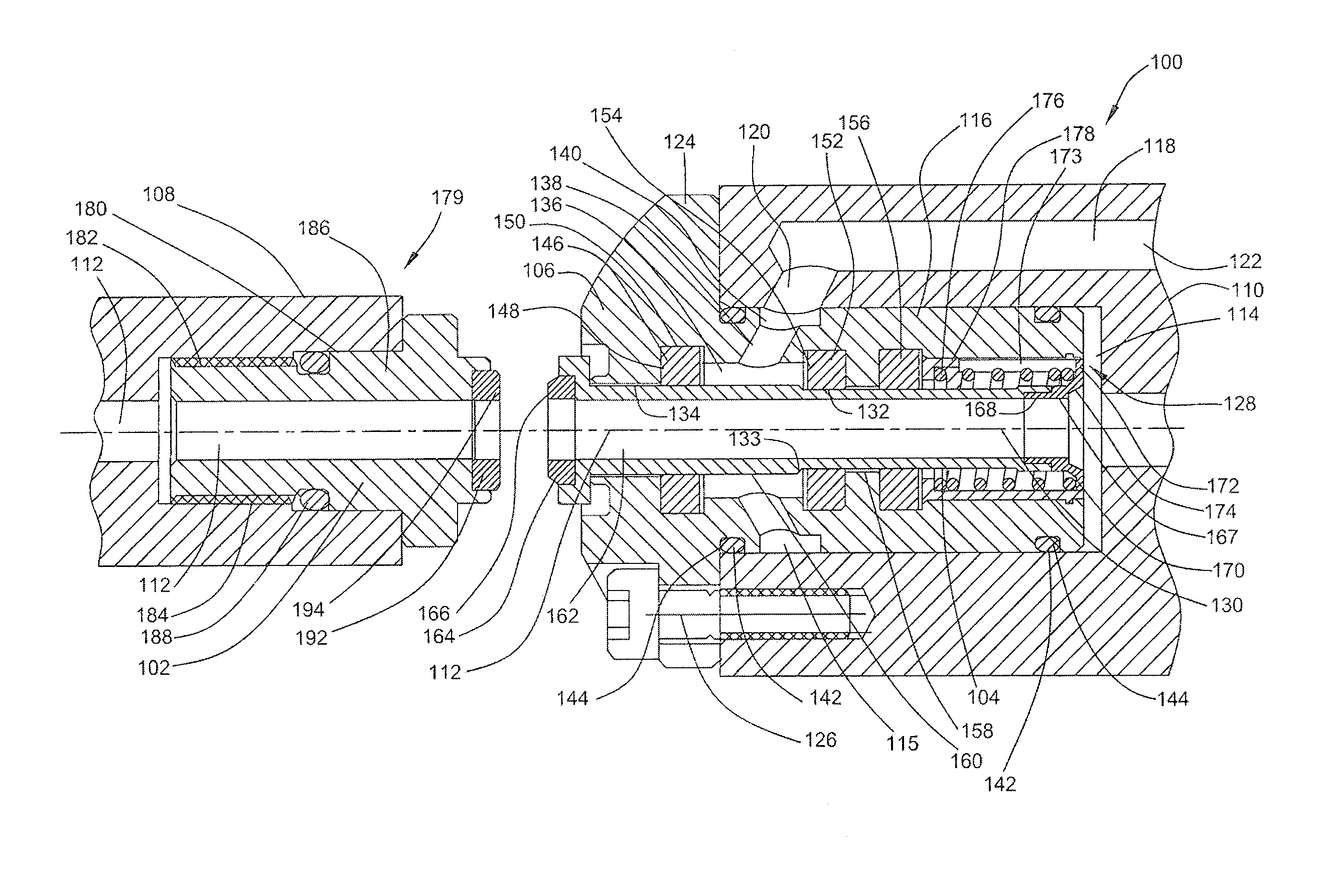
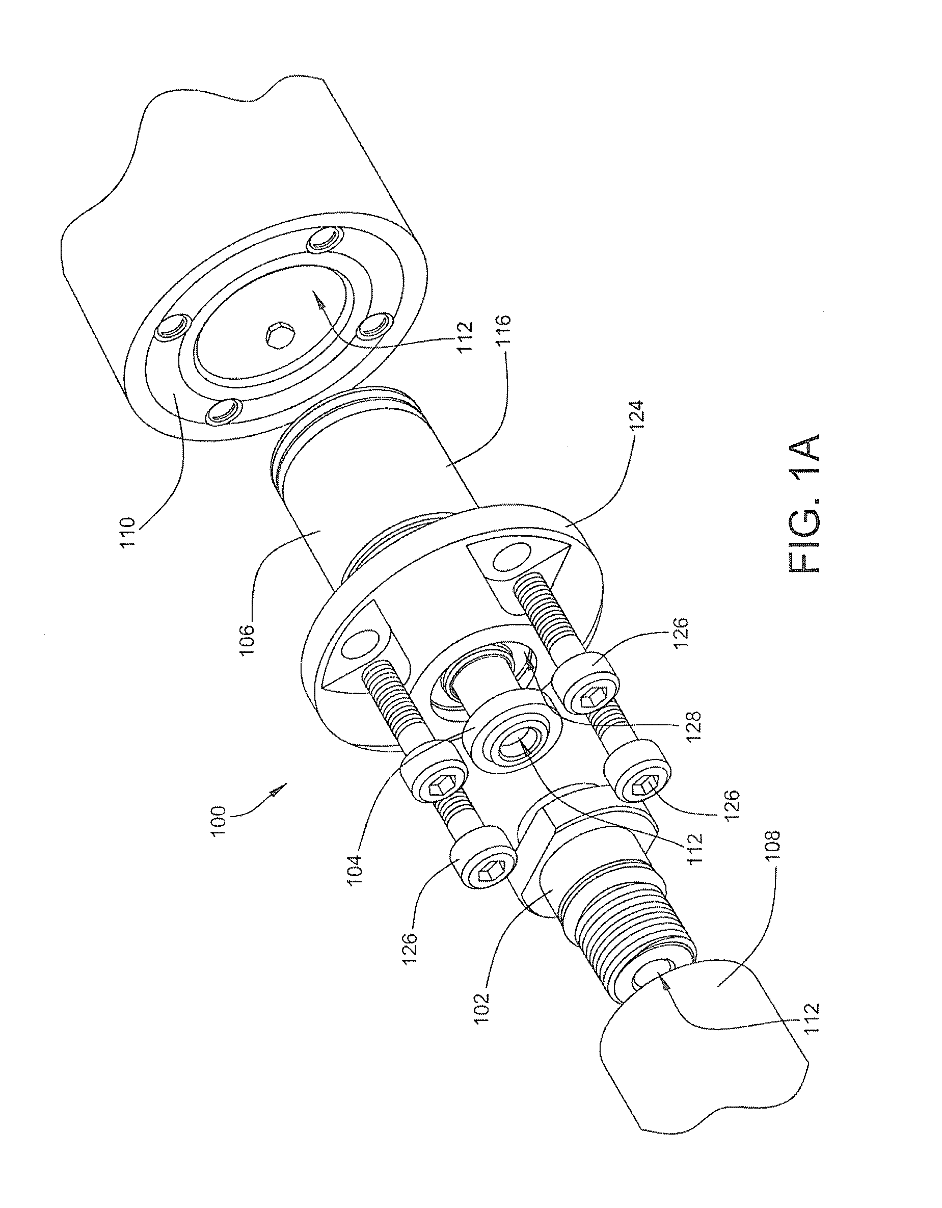
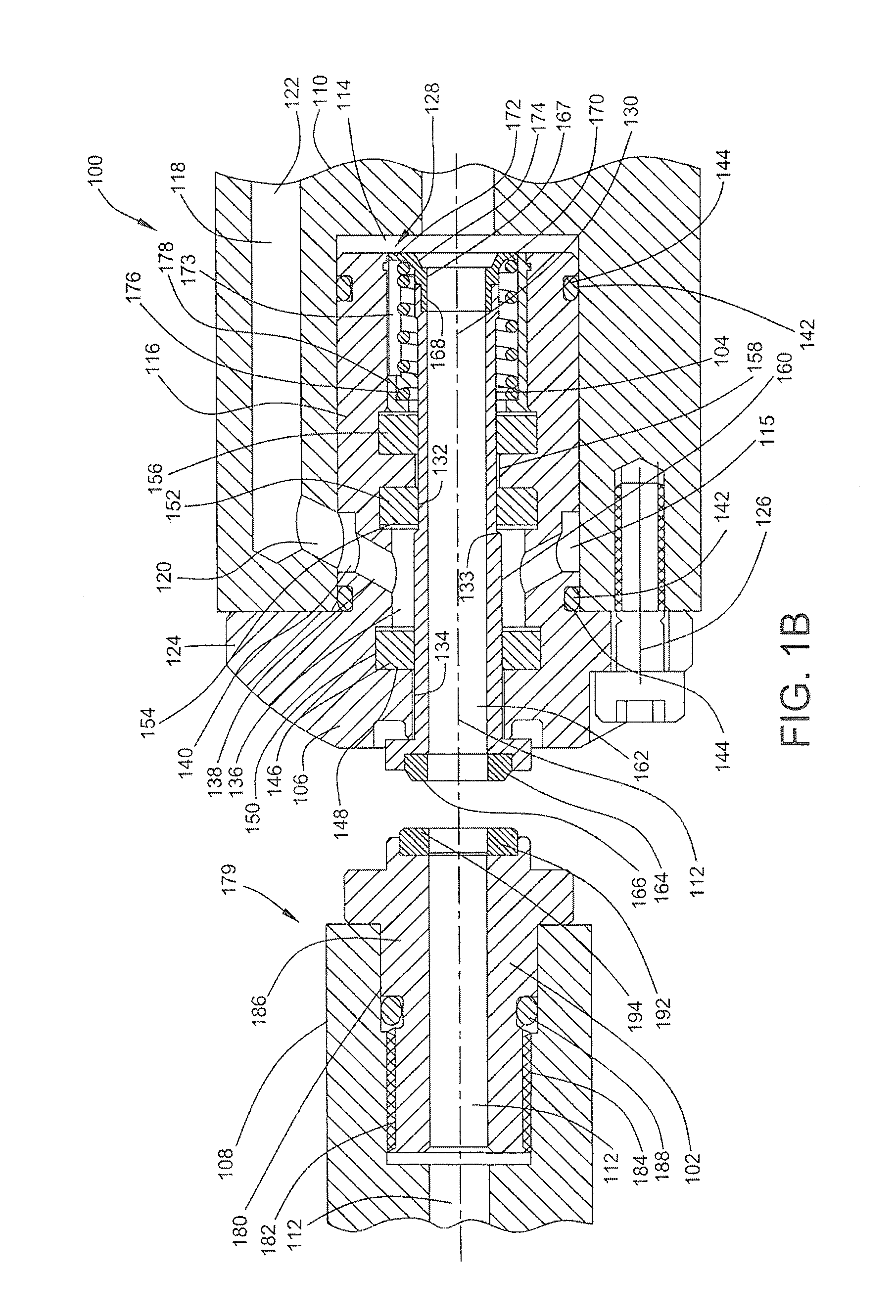
[0023]In the drawings, which form a part of this specification, FIG. 1A is an exploded isometric view of one embodiment of a rotary union 100. The rotary union 100 includes a rotating seal member 102 and a non-rotating seal member 104 that is axially moveable relative to a housing 106. The rotating seal member 102 is associated with a rotating machine component 108, and the housing 106 is associated with a non-rotating machine component 110. A segmented conduit or media channel 112 extends through the non-rotating machine component 110, the rotating and non-rotating seal members 102 and 104 respectively, and the rotating machine component 108 as is best illustrated in FIG. 1B, which is a cross section through the rotary union 100.

[0024]As shown in FIG. 1B, portions of the media channel 112 are defined in different components of the rotary union 100 to provide a fluid passageway through the rotating and non-rotating machine components 108 and 110 when the rotating and non-rotating se...


PUM


Abstract

A rotary union includes a non-rotating machine component having a receiving counterbore, a media channel opening, and a control channel. A housing is positioned within the receiving counterbore and has a bore and a control chamber in fluid communication with the control channel. A non-rotating seal member is slidably and sealingly disposed within the bore in the housing and has a media channel in fluid communication with the media channel opening and the receiving counterbore. The non-rotating seal member can be selectively extended or retracted within the bore of the housing, such that selective engagement of a face seal is accomplished under different operating conditions of the rotary union.

Description

TECHNICAL FIELD OF THE DISCLOSURE[0001]The present invention relates to fluid coupling devices such as rotary unions and, more particularly, to an improved seal control mechanism that operates with lubricating and non-lubricating media, as well as without media.BACKGROUND OF THE INVENTION[0002]Fluid coupling devices such as rotary unions are used in industrial applications, for example, machining of metals or plastics, work holding, printing, plastic film manufacture, papermaking, semiconductor wafer manufacture, and other industrial processes that require a fluid medium to be transferred from a stationary source such as a pump or reservoir into a rotating element such as a machine tool spindle, work-piece clamping system, or rotating drums or cylinder. Often these applications require relatively high media pressures, flow rates, or high machine tool rotational speeds.[0003]Rotary unions used in such applications convey fluid medium used by the equipment for cooling, heating, or for...

Claims


Application Information

Patent Timeline
Patent Type & Authority Patents(United States)
IPC IPC(8): F16L33/16
CPCF16L27/082Y10T137/86268Y10T137/87917Y10T137/0318F04B39/00F16D33/00F16D33/02F16D33/18
Inventor BURRUS, DAVIDLACROIX, GRAIG AARON
Owner DEUBLIN
Why Eureka
Try Eureka