Even-loading DPF and regeneration thereof

a technology of dpf and dpf, applied in the field of motor vehicle engineering, can solve the problems of reducing mechanical efficiency and fuel economy of engines, increasing the capacity of dpf may require increasing its length, or its diameter, and reducing engine performance and fuel economy, so as to improve thermal management during regeneration and reduce thermal gradients and mechanical stresses during regeneration. , the effect of reducing backpressur

Inactive Publication Date: 2013-05-21
FORD GLOBAL TECH LLC
View PDF42 Cites 4 Cited by
  • Summary
  • Abstract
  • Description
  • Claims
  • Application Information

AI Technical Summary

Benefits of technology

[0003]As a DPF accumulates soot, its capacity for continued accumulation is naturally reduced. Further, a DPF operating with too much accumulated soot will impart excessive backpressure to the exhaust flow, which may degrade engine performance and fuel economy. Therefore, a DPF may be configured to support one or more regeneration modes, which restore the capacity of the filter for continued soot trapping. Some diesel-engine systems are configured to temporarily increase the exhaust temperature to burn away soot accumulated in the DPF. This is done by increasing the amount of energy released into the exhaust as heat. Accordingly, an engine may operate at reduced mechanical efficiency and fuel economy during DPF regeneration. For a given engine system, a DPF of greater capacity requires less frequent regeneration, and so provides improved fuel economy.
[0005]U.S. Pat. No. 7,204,965 describes a DPF in which a cell structure open on both ends is arranged upstream of the half-open honeycomb structure described above. This configuration addresses the issue of excessive backpressure caused by soot clogging the DPF inlet. The present application, by contrast, describes a DPF system that not only reduces backpressure due to inlet clogging, but also enables improved thermal management during regeneration. More specifically, the system here disclosed is configured so that soot accumulation in the DPF is roughly even in the axial direction at the time of regeneration. In this manner, thermal gradients and mechanical stresses during regeneration are reduced.

Problems solved by technology

Further, a DPF operating with too much accumulated soot will impart excessive backpressure to the exhaust flow, which may degrade engine performance and fuel economy.
Accordingly, an engine may operate at reduced mechanical efficiency and fuel economy during DPF regeneration.
However, increasing the capacity of a DPF may require increasing its length, or its diameter, or both.
Packing constraints naturally limit the diameter of a DPF in a motor-vehicle engine system, and thermal-management constraints may limit its length.
If the accumulated soot is distributed unevenly with respect to the central axis of the filter, then the DPF may heat up unevenly—viz., a large thermal gradient may develop along the axis, resulting in unbalanced mechanical stress.
When the ratio is too high, ring-off crack failure may occur during regeneration.

Method used


Image

  • Even-loading DPF and regeneration thereof
  • Even-loading DPF and regeneration thereof
  • Even-loading DPF and regeneration thereof

Examples


Embodiment Construction

[0016]The subject matter of this disclosure is now described by example and with reference to the illustrated embodiments listed above. Components, process steps, and other elements that may be substantially the same in one or more embodiments are identified coordinately and are described with minimal repetition. It will be noted, however, that elements identified coordinately may also differ to some degree. It will be further noted that the drawing figures included in this disclosure are schematic and generally not drawn to scale. Rather, the various drawing scales, aspect ratios, and numbers of components shown in the figures may be purposely distorted to make certain features or relationships easier to see.

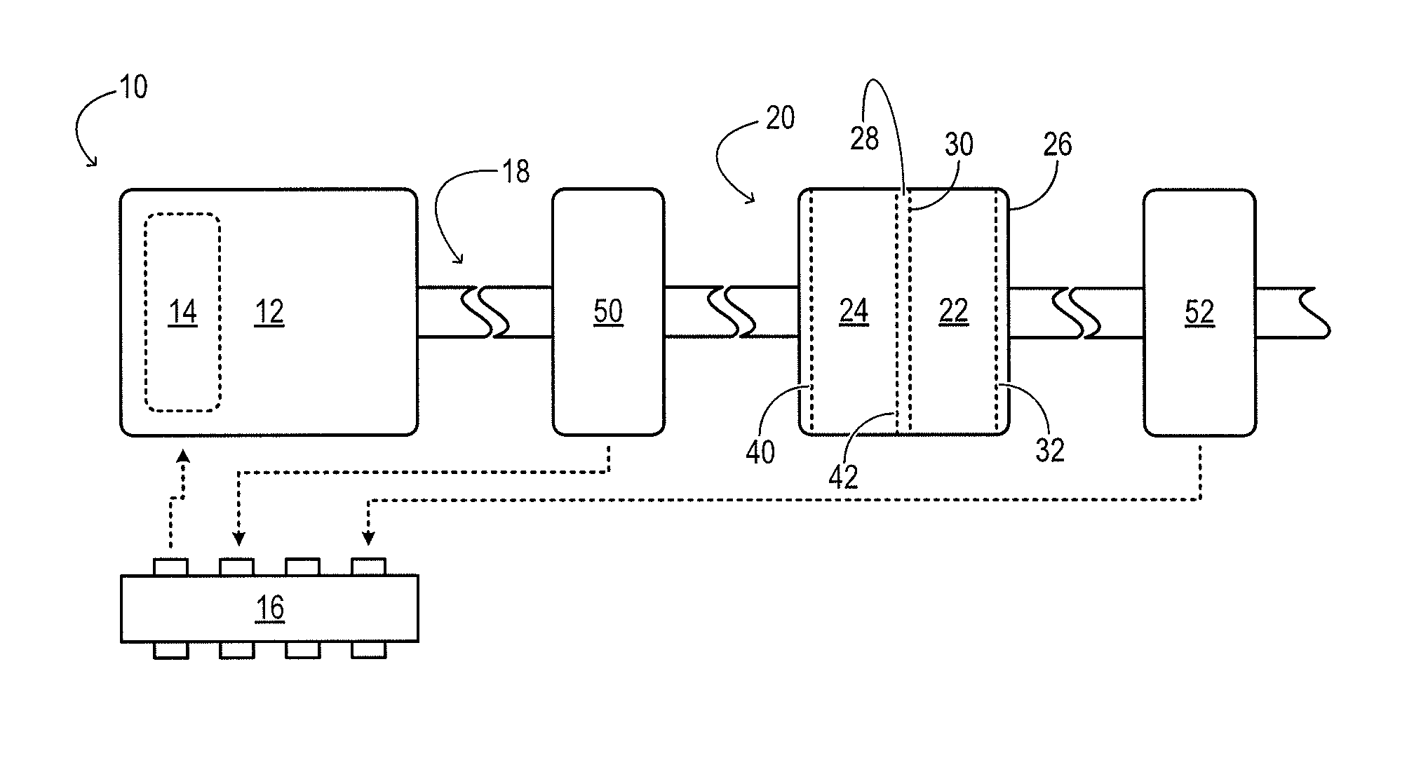
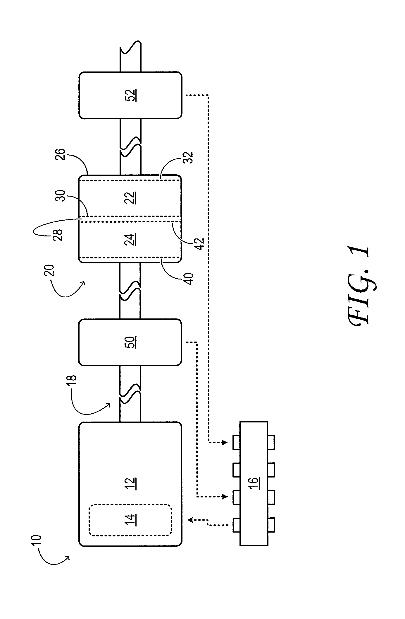
[0017]FIG. 1 schematically shows aspects of an example engine system 10 in one embodiment. The engine system includes engine 12, which admits air and fuel and generates mechanical power for driving a motor vehicle. In the illustrated embodiment, electronic fuel injectors 14 con...


PUM

PropertyMeasurementUnit
temperatureaaaaaaaaaa
exhaust-permeableaaaaaaaaaa
flow areaaaaaaaaaaa

Abstract

A motor-vehicle engine system comprises an envelope configured to transmit exhaust. The envelope encloses a first array of filtration cells downstream of a second array of filtration cells. The system further comprises a fuel injector configured to increase a temperature in the envelope when soot is evenly distributed between the first and second arrays in order to address thermal gradients.

Description

TECHNICAL FIELD[0001]This application relates to the field of motor vehicle engineering, and more particularly, to removing soot from motor-vehicle engine exhaust using a regenerable soot filter.BACKGROUND AND SUMMARY[0002]A diesel-engine system may include a soot filter or so-called diesel particulate filter (DPF). The DPF is configured to trap soot entrained in the engine exhaust. The DPF may include a honeycomb arrangement of hollow cells having exhaust-permeable walls. Each cell may extend in length from the inlet end of the filter to the outlet end of the filter. In a typical arrangement, each cell of the DPF is open at one end and closed at the other. Adjacent cells may be oriented alternately, such that a cell having an open inlet and closed outlet is adjacent one or more cells having closed inlets and open outlets. In this configuration, exhaust entering an open inlet of a cell is forced to cross one or more of the exhaust-permeable partitions into a cell having an open outl...

Claims


Application Information

Patent Timeline
Patent Type & Authority Patents(United States)
IPC IPC(8): B01D50/00F01N3/00B01D51/00B01D46/38B01D49/00B01D46/00B01D45/00B01D41/00B01D24/00B01D39/06B01D39/14
CPCF01N3/0253F01N9/002F01N13/0093F01N13/0097F01N3/035F01N3/2066F01N2560/06F01N2900/1406Y02T10/47F01N2330/60Y02A50/20Y02T10/40
Inventor ZHANG, XIAOGANG
Owner FORD GLOBAL TECH LLC
Why Eureka
Try Eureka