Eureka AIR delivers breakthrough ideas for toughest innovation challenges, trusted by R&D personnel around the world.

Method and apparatuses for pre-screening

a pre-screening and screening technology, applied in the direction of screening, chemistry apparatus and processes, solid separation, etc., can solve the problems of vibratory motors consuming significant power, screen wear and tear, etc., to reduce wear and damage, reduce cost, and reduce the effect of wear and damag

Active Publication Date: 2013-05-14
DERRICK CORP
View PDF14 Cites 38 Cited by
  • Summary
  • Abstract
  • Description
  • Claims
  • Application Information

AI Technical Summary

Benefits of technology

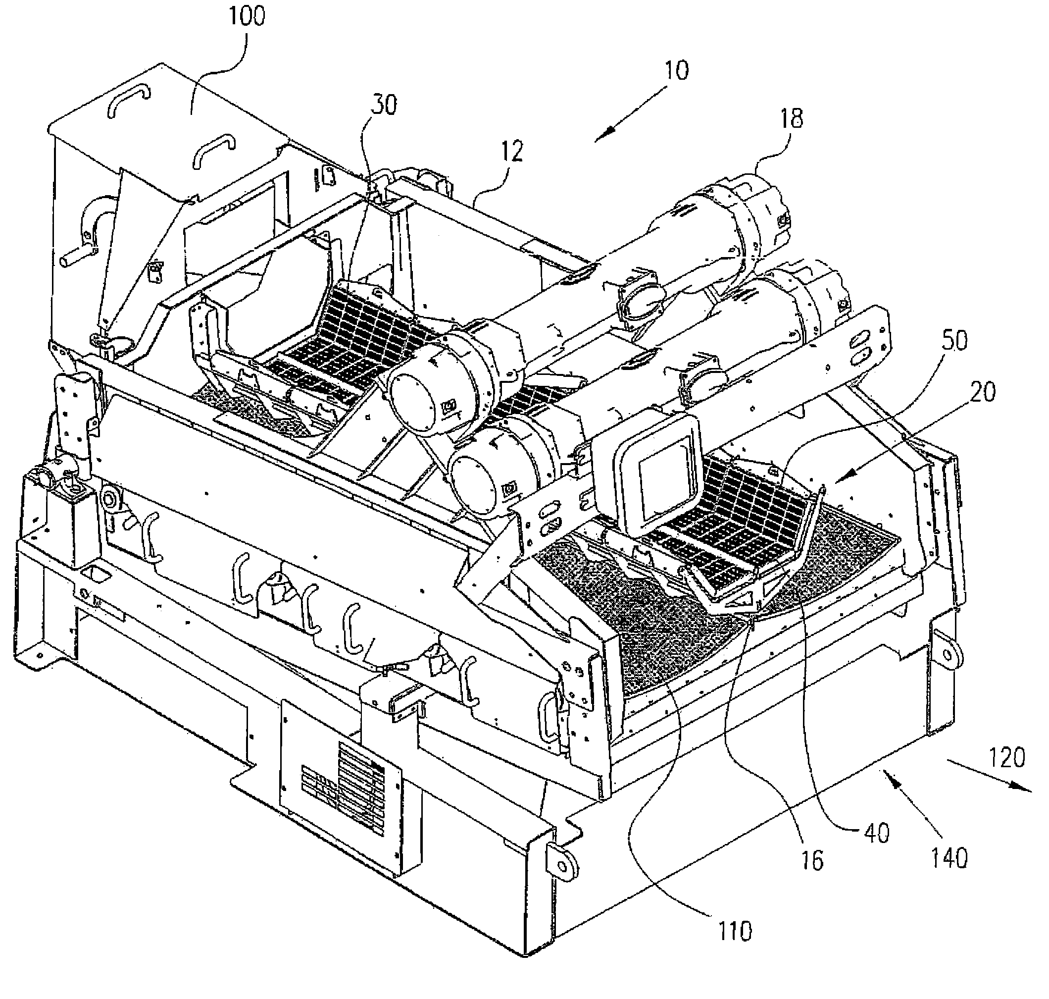
[0005]According to an example embodiment of the present invention, a vibratory screening machine provides for vibratory pre-screening of materials. Vibratory pre-screening reduces wear and damage to screens and provides for more effective screening. The vibratory screening machine includes a pre-screening assembly that is designed to be cost effective and can be easily installed on the vibratory screening machine. The pre-screening assembly includes screen assemblies that are configured to be quickly and easily replaced. The pre-screening assembly includes a pre-screening surface. The pre-screening surface may have a concave shape. The term concave as used herein is not limited to curved surfaces but includes any surface configured as a trough or other shape suitable for screening a material. The pre-screening assembly may be configured to be attached to a structural member of the vibratory screening machine such that vibrations of the machine are imparted to the pre-screening assembly. The pre-screening assembly may also be used independently of the vibratory screening machine. The pre-screening assembly may be configured with a pre-screen vibratory motor. The pre-screen vibratory motor may be directly or indirectly attached to the pre-screening assembly. The pre-screen motor may be configured to also provide vibrations to a primary screening surface / area of the vibratory screening machine. Such configurations may reduce the size of and / or eliminate the need for vibratory motors that are configured to vibrate a frame of the vibratory screening machine. The pre-screen vibratory motor may replace vibratory motors configured to vibrate the frame of the vibratory screening machine. The pre-screen vibratory motor may also substantially isolate vibrations to the pre-screening assembly and / or the primary screening surface.

Problems solved by technology

Over time, screens wear and require replacement.
Wear is often attributable to damage caused by oversized materials.
Such vibratory motors consume significant amounts of power.

Method used


Image

  • Method and apparatuses for pre-screening
  • Method and apparatuses for pre-screening
  • Method and apparatuses for pre-screening

Examples


Embodiment Construction

[0041]Like reference characters denote like parts in the drawings.

[0042]FIG. 1 shows a vibratory screening machine 10 with an installed pre-screening assembly 20. Material is fed into a feeder 100 and then directed onto a concave screening surface 30 of pre-screening assembly 20. Screen assemblies 50 form concave screening surface 30. Undersized material passes through screening surface 30 and onto a primary screening surface 110. Oversized materials are discharge from end 40 of pre-screening assembly 20. Material travels in flow direction 120 toward the vibratory screening machine 10 end 140. The material flowing inside pre-screening assembly 20 is contained within concave screening surface 30. The material may be dry, a slurry, etc.

[0043]Vibratory screening machine 10 includes wall members 12, a central member 16 and an acceleration arrangement 18. Central member 16 divides vibratory screening machine 10 into two screening areas. Vibratory screening machine 10 may, however, have o...


PUM


Abstract

A vibratory screening machine includes a primary screening area and a pre-screening assembly including a frame and screen assemblies. The screen assemblies are secured to the frame and form a pre-screening surface. The frame is attached to the vibratory screening machine such that the concave pre-screening surface is above the primary screening area.

Description

[0001]This application claims the benefit of U.S. Provisional Patent Application No. 60 / 919,417, filed Mar. 21, 2007, the contents of which are incorporated herein by reference.FIELD OF THE INVENTION[0002]The present invention relates generally to material screening. More particularly, the present invention relates to a method and apparatuses for pre-screening.BACKGROUND INFORMATION[0003]Material screening includes the use of vibratory screening machines. Vibratory screening machines provide the capability to excite an installed screen such that materials placed upon the screen may be separated to a desired level. Oversized materials are separated from undersized materials. Over time, screens wear and require replacement. Wear is often attributable to damage caused by oversized materials.[0004]In order to excite an installed screen, existing vibratory screening machines include vibratory motors. The vibratory motors are attached to a frame of the vibratory screening machine and are ...

Claims


Application Information

Patent Timeline
Patent Type & Authority Patents(United States)
IPC IPC(8): B07B1/49
CPCB07B1/30B07B1/42B07B1/28B07B1/4609B07B1/46
Inventor WOJCIECHOWSKI, KEITH F.NEWMAN, CHRISTIAN
Owner DERRICK CORP
Why Eureka
Eureka Blog
Learn More