
Micro manipulator for electrode movement in neural signal recording

a neural signal and micro-manipulator technology, applied in the field of micro-manipulator for electrode movement, can solve the problems of deteriorating electrode positioning ability, difficult experiment, and inability to perform electric stimulation on the human body, and achieve the effects of simple structure, easy attachment and small siz

Inactive Publication Date: 2013-05-07
KOREA INST OF SCI & TECH
View PDF10 Cites 5 Cited by
  • Summary
  • Abstract
  • Description
  • Claims
  • Application Information

AI Technical Summary

Benefits of technology

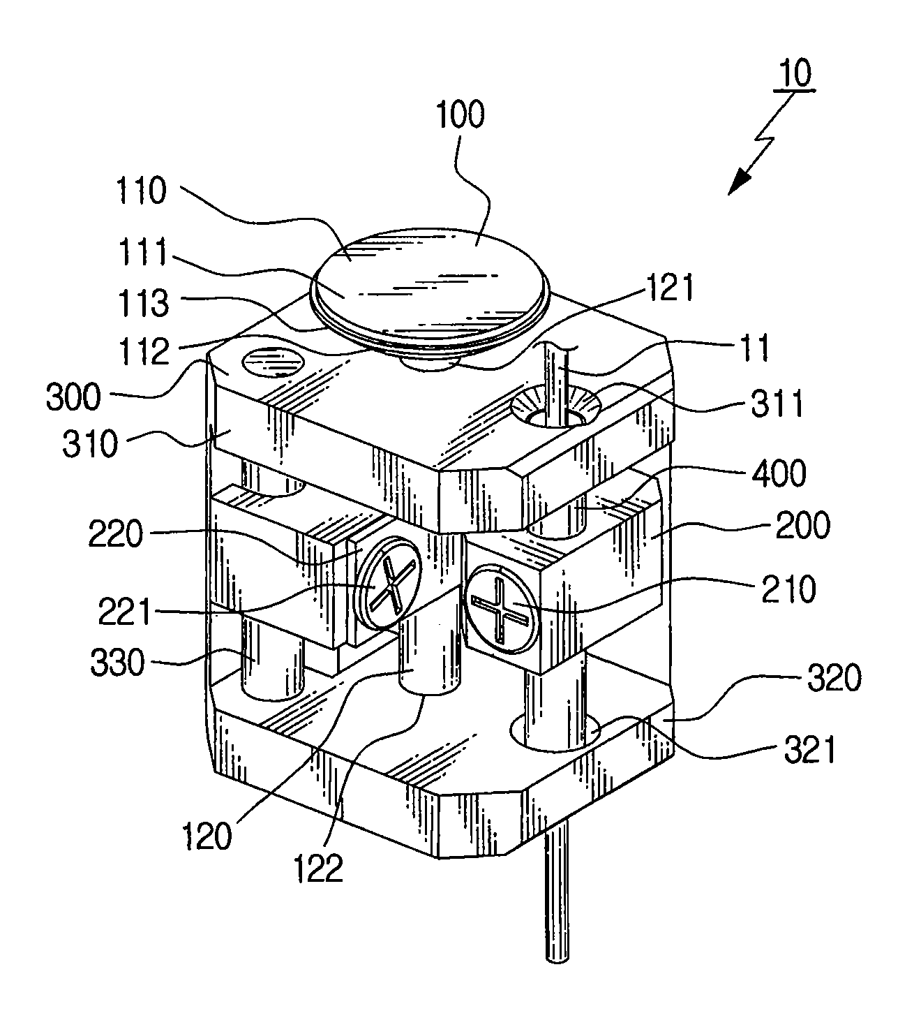
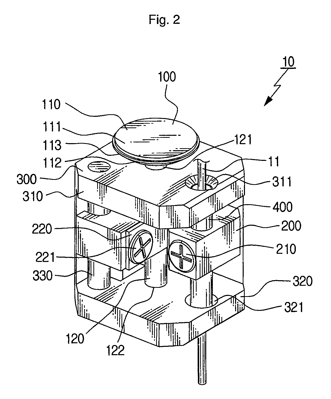
The patent is about a small manipulator that can be easily attached to a small object and has very precise movement. It uses a motor and a vibration part to move an electrode connected to the object. This manipulator has a simple structure, is small in size, and can perform precise experiments.

Problems solved by technology

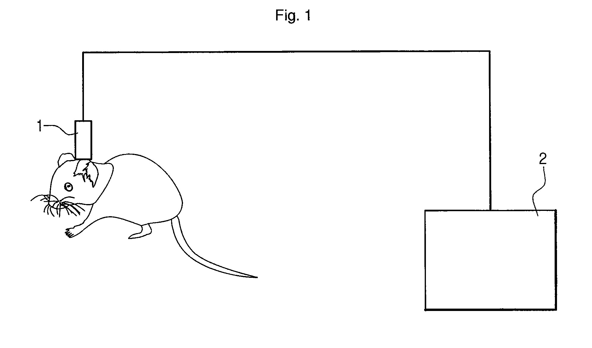
However, since the electrical stimulation method cannot be performed on the human, experiments are carried out on animals.
Accordingly, the experiment is difficult, and the positioning ability of the electrode deteriorates due to the manual operation.
In addition, a problem arises in that the electrode may be detached from the neuron to be recorded due to the subject animal's resistance.
However, since the known micro manipulator includes a gear portion transmitting an operation of the motor, a moving device such as a screw used for the linear movement of the electrode, and the like, a problem arises in that a longitudinal length of the manipulator increases and a structure is complex.
In addition, since an error occurs easily in a meshing operation between various mechanical components such as reduction gears and a screw, a problem arises in that the resolution of the micro manipulator for moving the electrode is not high and the control ability deteriorates due to the low resolution.

Method used


Image

  • Micro manipulator for electrode movement in neural signal recording
  • Micro manipulator for electrode movement in neural signal recording
  • Micro manipulator for electrode movement in neural signal recording

Examples


Embodiment Construction

[0042]Exemplary embodiments now will be described more fully hereinafter with reference to the accompanying drawings, in which exemplary embodiments are shown. This disclosure may, however, be embodied in many different forms and should not be construed as limited to the exemplary embodiments set forth therein. Rather, these exemplary embodiments are provided so that this disclosure will be thorough and complete, and will fully convey the scope of this disclosure to those skilled in the art. In the description, details of well-known features and techniques may be omitted to avoid unnecessarily obscuring the presented embodiments.

[0043]Unless otherwise defined, all terms (including technical and scientific terms) used herein have the same meaning as commonly understood by one of ordinary skill in the art. It will be further understood that terms, such as those defined in commonly used dictionaries, should be interpreted as having a meaning that is consistent with their meaning in the...


PUM


Abstract

This disclosure relates to a micro manipulator having a simple structure and having high possibility of recording a biological signal of a neuron at a desired position by improving positioning resolution of an electrode disposed adjacent to a subject's brain neuron or an electrode holder attached with the electrode. The micro manipulator according to the disclosure includes: a motor which includes a shaft and a vibration portion; a mobile which is connected to the shaft so as to be movable along the shaft; and a frame which supports the motor, wherein an electrode is connected to the mobile in a direction parallel to a longitudinal direction of the shaft, and wherein when the mobile moves linearly in accordance with a vibration of the shaft due to the vibration portion, the electrode moves linearly.

Description

CROSS-REFERENCE TO RELATED APPLICATIONS[0001]This application claims priority to Korean Patent Application No. 10-2008-0135977, filed on Dec. 29, 2008, and all the benefits accruing therefrom under 35 U.S.C. §119, the contents of which in its entirety are herein incorporated by reference.BACKGROUND[0002]1. Field[0003]This disclosure relates to a micro manipulator for an electrode movement, and more particularly, to a micro manipulator capable of improving positioning resolution and positioning ability of an electrode disposed adjacent to a subject's neuron or an electrode holder attached with the electrode with a simple structure.[0004]2. Description of the Related Art[0005]A living organism has numerous neurons, and the neurons are used as information transmitting means. A method of transmitting information between neurons is understood as an electrical signal transmitting and receiving process. That is, the neurons transmit information to other neurons via an electrical signal. Th...

Claims


Application Information

Patent Timeline
Patent Type & Authority Patents(United States)
IPC IPC(8): A61B19/00
CPCA61B19/201A61B5/065A61N1/0529A61B5/04001A61B2017/00398A61B2019/5251A61B5/0051A61B90/11A61B2034/2051A61B5/24A61B5/251A61B5/291A61B5/0006A61B2562/0209
Inventor YOON, EUI SUNGYANG, SUNG WOOKKIM, JIN SEOKRHO, DUK MOONPARK, KI TAELEE, SE MINCHO, JEI WONSHIN, HEE SUP
Owner KOREA INST OF SCI & TECH
Learn More