
Onboard sensor suite for determining projectile velocity

a technology of projectile velocity and sensor suite, applied in the field of munitions, can solve the problems of measurement bias error in velocity estimation, inability to use gps measurements for all applications, and inability to meet the requirements of gps measurement accuracy, etc., and achieve the effect of more accurate function

Inactive Publication Date: 2013-04-30
UNITED STATES OF AMERICA THE AS REPRESENTED BY THE SEC OF THE ARMY
View PDF5 Cites 12 Cited by
  • Summary
  • Abstract
  • Description
  • Claims
  • Application Information

AI Technical Summary

Benefits of technology

The invention is an onboard sensor suite for long range precision performance of munitions. It measures the projectile airspeed to estimate its velocity, allowing for precise positioning and improved trajectory correction. The sensor suite is small, simple, and not affected by external signals such as GPS jamming. It provides fast updates and allows for sophisticated signal processing. It can be used with munitions that either have a guidance system or not. The sensor suite helps air bursting munitions to have more accurate fuze airburst times.

Problems solved by technology

These estimates are typically processed from accelerometer measurements, which could lead to measurement bias errors in the velocity estimates.
Although the conventional solutions have proven to be satisfactory, they are faced with certain limitations.
As an example, GPS measurements cannot be used for all applications since some projectiles might not be readily equipped with GPS.
More specifically, using GPS measurements for a projectile might be unacceptable for at least the following two reasons: First, if the projectile is not already equipped with GPS capability, fitting an entirely new, typically complicated GPS system, into the existing design might be problematic.
As another example, Doppler radar measurements might be limited to certain types of projectiles.
More specifically, using a Doppler radar might in certain circumstances be unsatisfactory, particularly if the projectile is not equipped with a radar seeker, or if the projectile does not have sufficient capability or physical space to enable the addition of a new radar seeker.
The need for such an onboard sensor suite has heretofore remained unsatisfied.

Method used


Image

  • Onboard sensor suite for determining projectile velocity
  • Onboard sensor suite for determining projectile velocity
  • Onboard sensor suite for determining projectile velocity

Examples


Embodiment Construction

[0026]FIG. 1 portrays an exemplary projectile 100 which includes an onboard proximity sensor suite 101, a body 105, a nose or forward section 150, and an aft section 155. The shape and design of the projectile 100 that is illustrated in FIG. 1 is merely for illustration purpose. It should be understood that the present invention could be incorporated as part of projectiles or munitions with different shapes and designs.

[0027]According to a preferred embodiment of the present invention, the proximity sensor suite 101 measures the velocity of the projectile 100 as it exits a weapon muzzle 160 (shown in dashed lines). This velocity is referred to herein as projectile muzzle velocity.

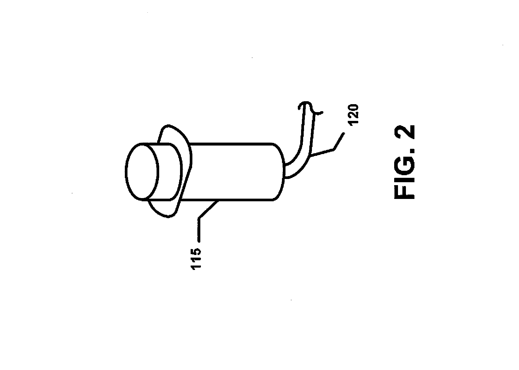
[0028]The proximity sensor suite 101 generally includes a plurality of proximity sensors 110, 115 that are disposed along the projectile body 105. The proximity sensor suite 101 further includes a wire harness 120 that connects the proximity sensors 110, 115 to a central processing unit (CPU) or computer 12...


PUM


Abstract

An onboard sensor suite generally includes two main components: a proximity sensor suite for measuring the projectile muzzle velocity; and a pressure sensor suite for measuring the projectile airspeed. The flight velocity of the projectile can then be estimated with a high degree of accuracy using either the muzzle velocity by itself or the airspeed by itself, or, in a preferred embodiment, by using both the muzzle velocity and the airspeed. The proximity sensor suite includes proximity sensors that are mounted along a projectile body; a wire harness; and an onboard computer or CPU. The pressure sensor suite includes a Pitot pressure transducer and two static pressure transducers that are mounted within the projectile body; a wire harness; and a CPU.

Description

GOVERNMENTAL INTEREST[0001]The invention described herein may be manufactured and used by or for the Government of the United States for U.S. Government purposes.FIELD OF THE INVENTION[0002]The present invention relates in general to the field of munitions. More specifically, this invention relates to onboard sensors and associated method to determine the munition velocity by measuring parameters that are directly related to the munition flight velocity in a continuous manner during flight, without relying on external systems or signals. The onboard sensors predict the projectile position accurately and improve the performance of mid-course trajectory correction.BACKGROUND OF THE INVENTION[0003]A control system for a projectile often requires a measurement of the projectile velocity, in order to improve the projectile navigation and accuracy. The need for the projectile velocity has become increasingly important due to the desire for accuracy, particularly at longer ranges. Conventi...

Claims


Application Information

Patent Timeline
Patent Type & Authority Patents(United States)
IPC IPC(8): G05D1/00
CPCF42B15/01G01P3/665G01P5/16F41G7/34
Inventor RECCHIA, THOMASTOLEDO, WILFREDOCAHAYLA, JASONSCHEPER, ERIC
Owner UNITED STATES OF AMERICA THE AS REPRESENTED BY THE SEC OF THE ARMY
Learn More