Input overvoltage protection circuit with soft-start function
a protection circuit and function technology, applied in the direction of emergency protection arrangements, electrical equipment, emergency protection arrangements for limiting excess voltage/current, etc., can solve problems such as failure and/or circuit malfunction, and achieve the effect of suppressing the sudden change of load
- Summary
- Abstract
- Description
- Claims
- Application Information
AI Technical Summary
Benefits of technology
Problems solved by technology
Method used
Image
Examples
first exemplary embodiment
[First Exemplary Embodiment]
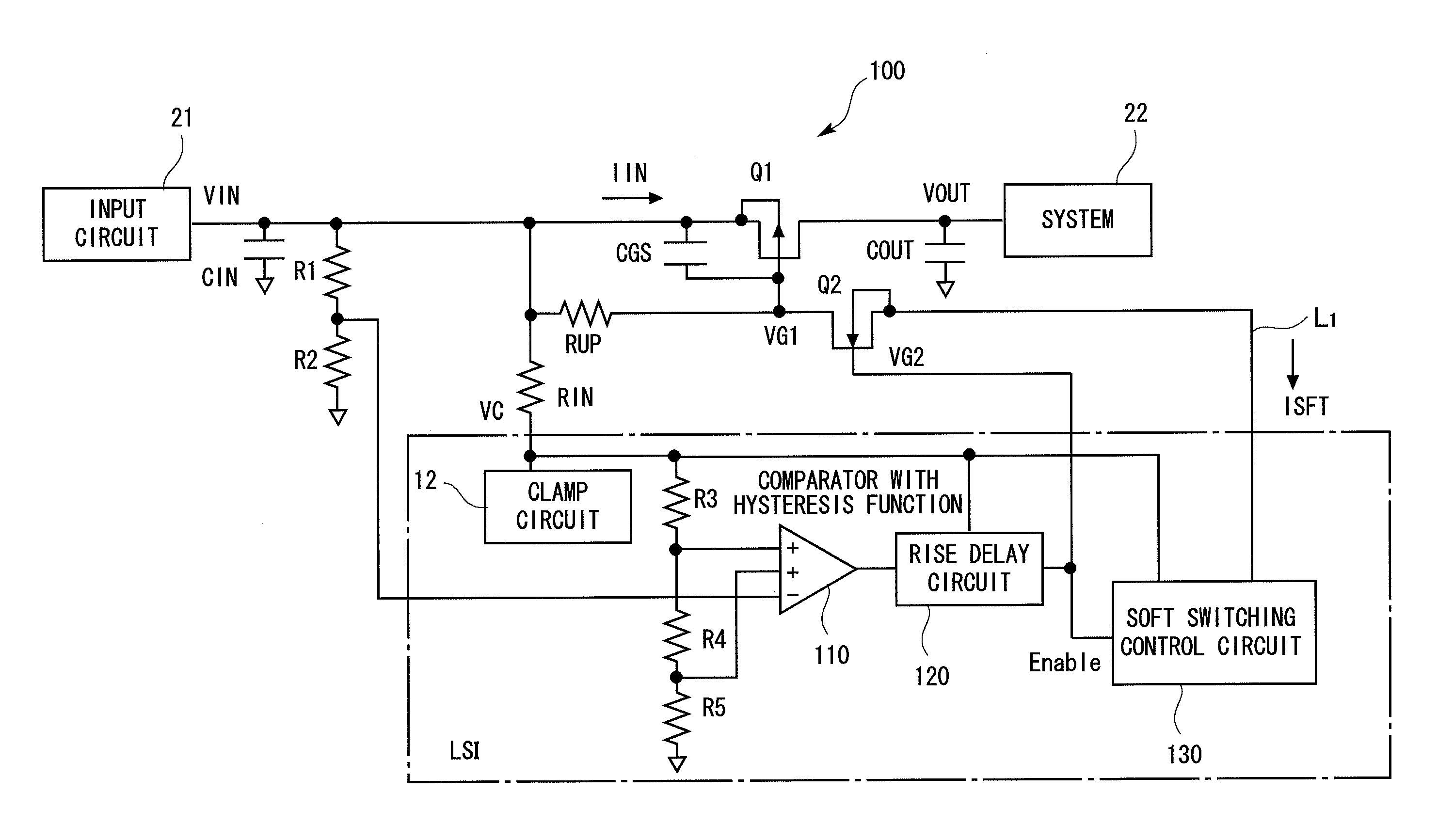
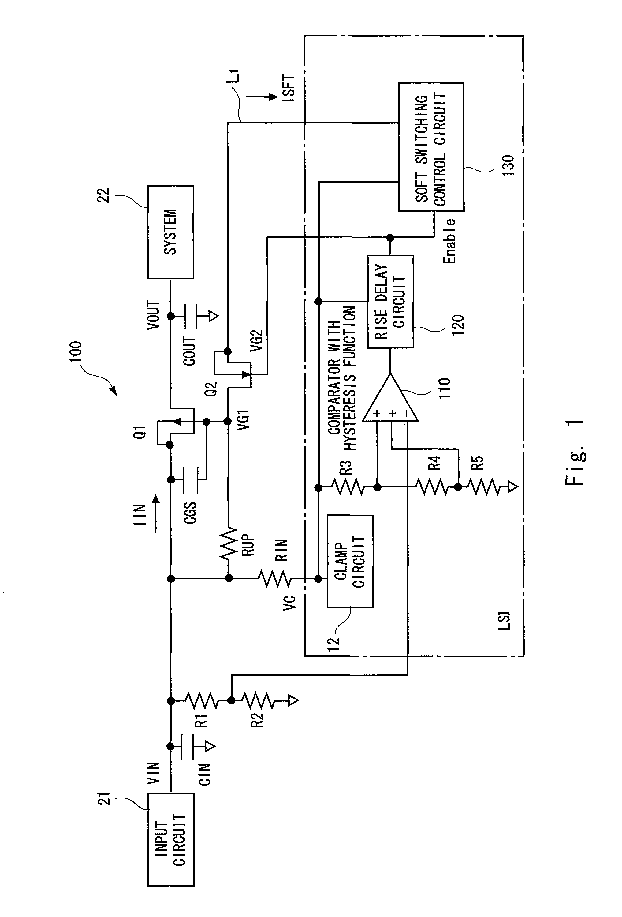
[0032]A first exemplary embodiment of an overvoltage protection circuit in accordance with the present invention is explained hereinafter. FIG. 1 shows an overvoltage protection circuit with a soft start function in accordance with a first exemplary embodiment. The overvoltage protection circuit 100 includes a PMOS transistor Q1 (first switch) to separate a system 22 from an input circuit 21, voltage-dividing resistors R1 and R2 to monitor an input voltage VIN, a comparator 110 to determine the overvoltage of the input voltage VIN, voltage-dividing resistors R3, R4 and R5 to generate a comparison reference voltage, an input resistor RIN, and a clamp circuit 12.
[0033]Further, in this first exemplary embodiment, the overvoltage protection circuit 100 also includes a rise delay circuit 120 that waits until the circuit is stabilized on startup, a soft switching control circuit 130 to implement a soft switching of the PMOS transistor Q1, a pull-up resistor RUP...
first modified embodiment
[First Modified Embodiment]
[0046]Note that although the configuration shown in FIG. 2 is shown as an example of the soft switching control circuit in the above-described exemplary embodiment, a soft switching control circuit 140 having a configuration shown in FIG. 7 can be also applied as a modified embodiment. Assume that the current source IREF has a fixed value in FIG. 7. That is, the current source IREF is supposed to appear at the output node D21 of a fourth current mirror 142 by a third current mirror 141 and the fourth current mirror 142. Further, the output of the third current mirror 141 is connected to the input of the fourth current mirror 142 through a switch SW5. Further, the output node D21 of the fourth current mirror 142 is connected to a line L1, which is connected to the gate of the PMOS transistor Q1, through a switch SW6. The On-Off states of the switches SW5 and SW6 are controlled by an Enable signal.
[0047]Further, a comparator 143, whose negative and positive ...
second exemplary embodiment
[Second Exemplary Embodiment]
[0050]Next, a second exemplary embodiment is explained. It has been explained that with a configuration in accordance with the first exemplary embodiment, the voltage drop is prevented by a soft start and that the leakage of the overvoltage can be prevented even when the voltage rises sharply to the overvoltage state. However, since the pull-up resistor RUP and the capacitance CGS are provided to maintain the PMOS transistor Q1 in the Off-state in the first exemplary embodiment, there is a possibility that the PMOS transistor Q1 could takes a relatively long time to change from an On-state to an Off-state. For example, if the input voltage VIN reaches an overvoltage after the PMOS transistor Q1 is once completely turned on, there is a possibility that the overvoltage could leak to the system 22. To begin with, this problem is explained with reference to a timing chart shown in FIG. 9.
[0051]FIG. 9 is a graph for explaining an operation of the first exempl...
PUM
 Abstract
Description
Claims
Application Information
 - R&D
- Intellectual Property
- Life Sciences
- Materials
- Tech Scout
- Unparalleled Data Quality
- Higher Quality Content
- 60% Fewer Hallucinations
Browse by: Latest US Patents, China's latest patents, Technical Efficacy Thesaurus, Application Domain, Technology Topic, Popular Technical Reports.
© 2025 PatSnap. All rights reserved.Legal|Privacy policy|Modern Slavery Act Transparency Statement|Sitemap|About US| Contact US: help@patsnap.com


