
Systems and methods for the electrodeposition of a nickel-cobalt alloy

Inactive Publication Date: 2013-04-23
NASA
View PDF17 Cites 3 Cited by
  • Summary
  • Abstract
  • Description
  • Claims
  • Application Information

AI Technical Summary

Benefits of technology

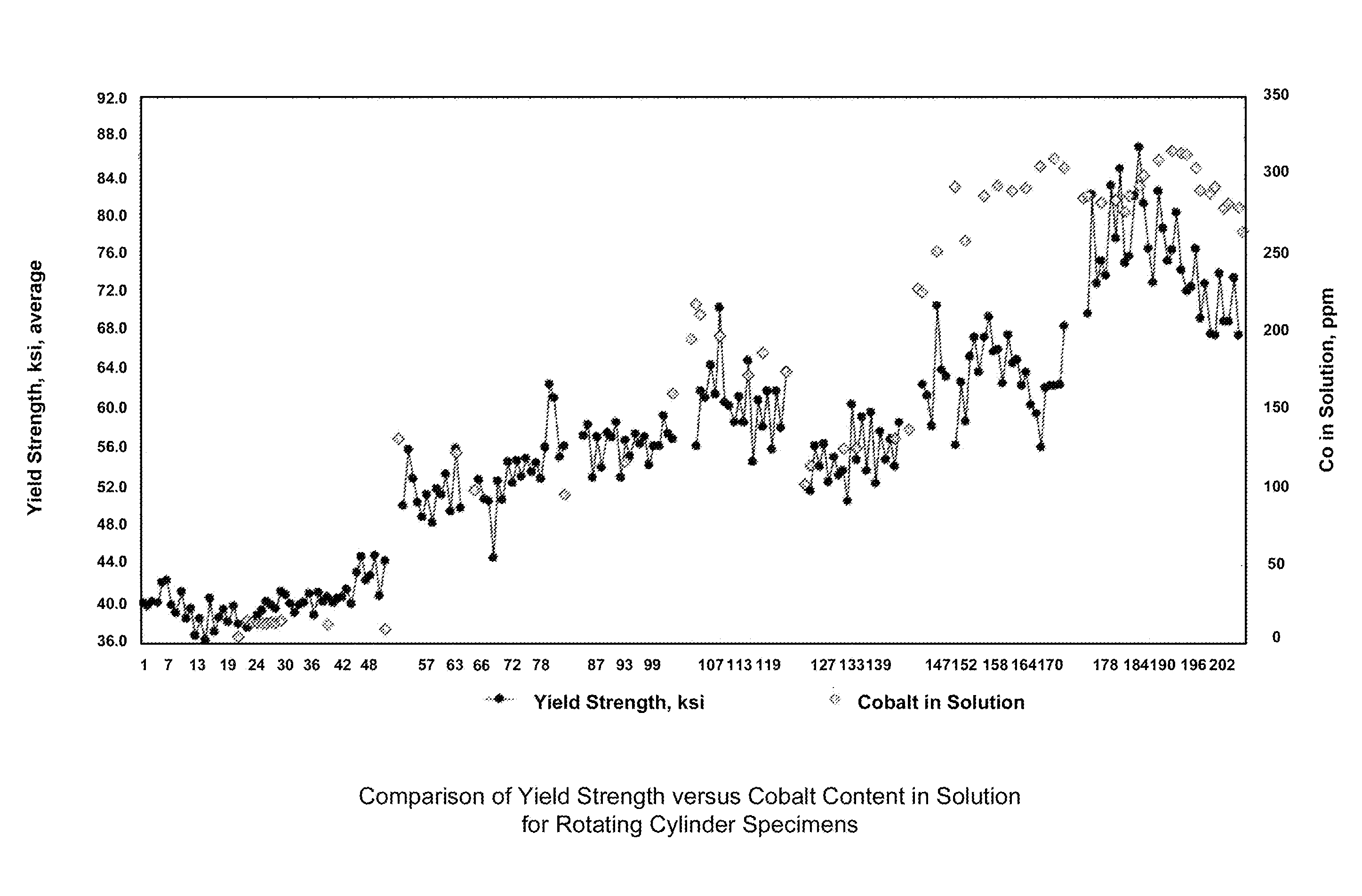
The patent describes a method for electrodeposition plating that allows for the co-deposition of cobalt and nickel to create an alloy with increased yield strength that maintains strain and weldability. The method does not require a rotating cylinder, which can be used to monitor the mechanical properties of the alloy during the plating operation. The deposit can be analyzed for its mechanical and chemical properties without sacrificing the part. Additionally, the method aims to enhance the tensile strength of the deposit by co-depositing cobalt at low levels.

Problems solved by technology

A drawback to bright nickel is that the brighter the deposit gets, the less ductile it becomes.
These interruptions create additional problems when plating resumes by requiring exacting surface preparation procedures to ensure the subsequent nickel layers bond adequately.
In addition, each additional plating cycle increases fabrication time and production costs.
However, a deposit containing 10% cobalt is too brittle for structural applications and results in a part that is not readily weldable.

Method used


Image

  • Systems and methods for the electrodeposition of a nickel-cobalt alloy
  • Systems and methods for the electrodeposition of a nickel-cobalt alloy
  • Systems and methods for the electrodeposition of a nickel-cobalt alloy

Examples


Embodiment Construction

[0036]For the purpose of promoting an understanding of the present invention, references are made in the text to exemplary embodiments of systems and methods for the electrodeposition of a nickel-cobalt alloy, only some of which are described herein. It should be understood that no limitations on the scope of the invention are intended by describing these exemplary embodiments. One of ordinary skill in the art will readily appreciate that alternate but functionally equivalent materials, components, and placement may be used. The inclusion of additional elements may be deemed readily apparent and obvious to one of ordinary skill in the art. Specific elements disclosed herein are not to be interpreted as limiting, but rather as a basis for the claims and as a representative basis for teaching one of ordinary skill in the art to employ the present invention.

[0037]It should be understood that the drawings are not necessarily to scale; instead, emphasis has been placed upon illustrating ...


PUM

PropertyMeasurementUnit
Fractionaaaaaaaaaa
Fractionaaaaaaaaaa
Fractionaaaaaaaaaa

Abstract

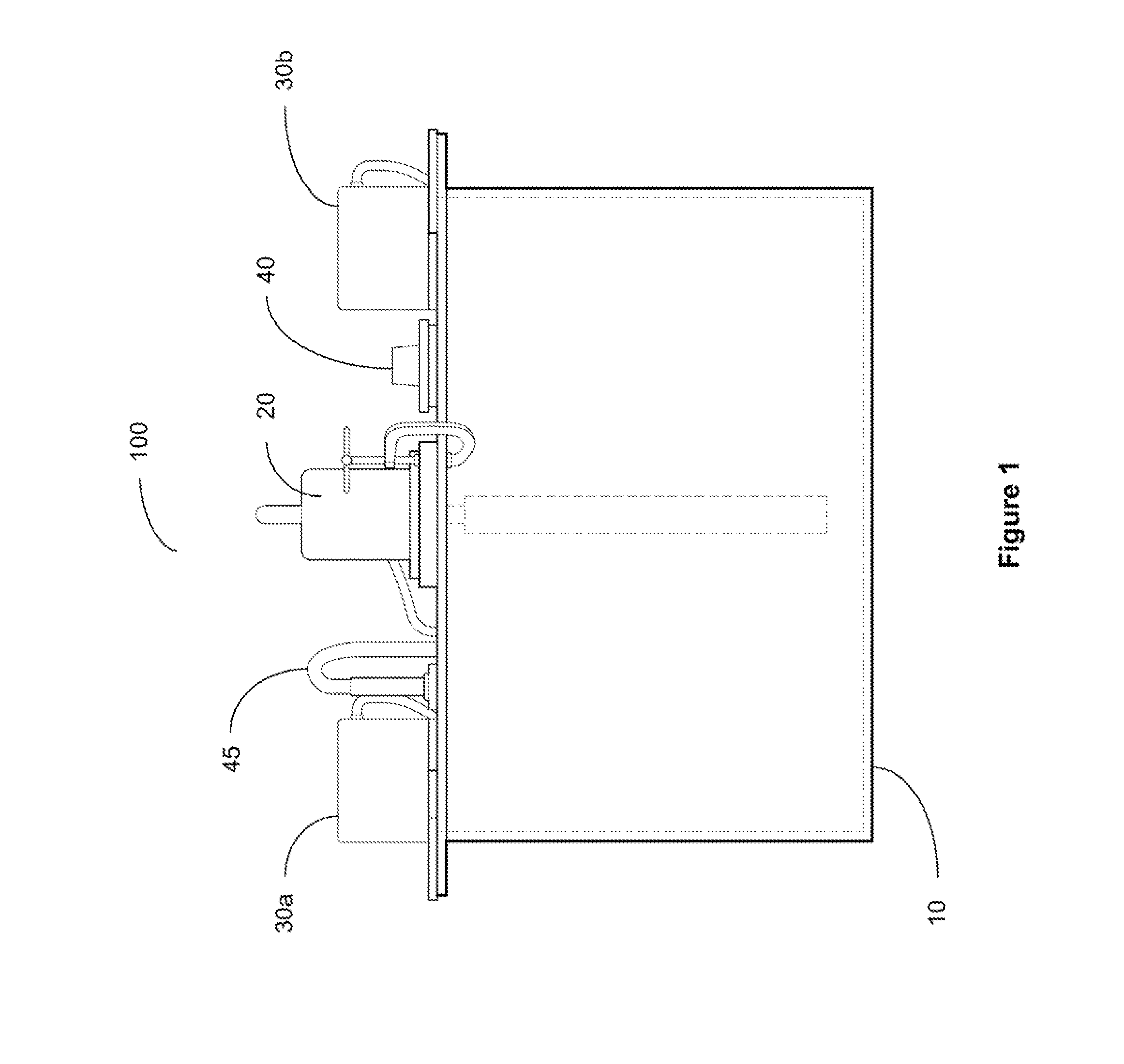
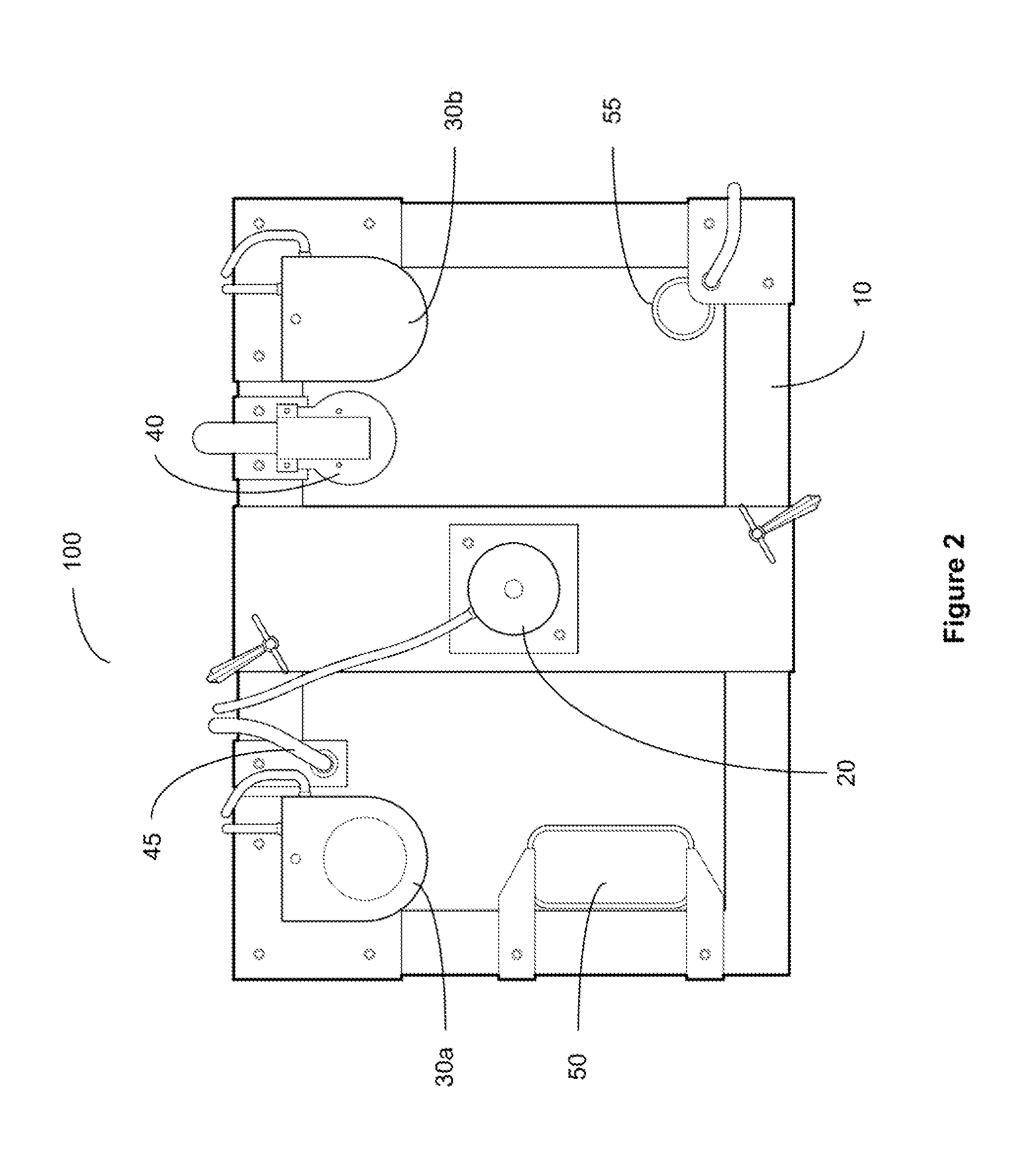
Systems and methods for electrodepositing a nickel-cobalt alloy using a rotating cylinder electrode assembly with a plating surface and an electrical contact. The assembly is placed within a plating bath and rotated while running a plating cycle. Nickel-cobalt alloy deposition is selectively controlled by controlling current density distribution and / or cobalt content in the plating bath while running the plating cycle to deposit an alloy of a desired yield strength onto the plating surface in a single plating cycle. In various embodiments, the rotating cylinder may be used as an insitu monitoring method to assist in obtaining the properties desired.

Description

FEDERAL RESEARCH STATEMENT[0001]The invention described herein was made in the performance of work under a NASA contract and by an employee of the United States Government and is subject to the provisions of Section 305 of the National Aeronautics and Space Act of 1958, as amended, Public Law 85-568 (72 Stat. 435, 42 U.S.C. §2457), and may be manufactured and used by or for the Government for governmental purposes without the payment of any royalties thereon or therefore.BACKGROUND OF THE INVENTION[0002]Electroplating is primarily used for depositing a layer of material to bestow a desired property (e.g., abrasion and wear resistance, corrosion protection, lubricity, aesthetic qualities) to a surface that otherwise lacks that property. Another application uses electroplating to build up thickness on undersized parts. The process used in electroplating is called electrodeposition.[0003]Nickel is a silver-white metal that is electrodeposited onto surfaces in a variety of industries in...

Claims


Application Information

Patent Timeline
IPC IPC(8): C25D21/14C25D21/16
CPCC25D21/14C25D3/562C25D5/04C25D21/10C25D21/12
Inventor OGOZALEK, NANCE JOWISTRAND, RICHARD E.
Owner NASA
Learn More