
Melting and refining in tanks with cooled walls

a technology of melting and refining tanks and walls, which is applied in the direction of electric/magnetic/electromagnetic heating, tank furnaces, furnaces, etc., can solve the problems of large amount of energy withdrawn from glass melt, increased difference, and increased energy loss through dissipation of hea

Inactive Publication Date: 2013-04-23
SCHOTT AG
View PDF17 Cites 29 Cited by
  • Summary
  • Abstract
  • Description
  • Claims
  • Application Information

AI Technical Summary

Benefits of technology

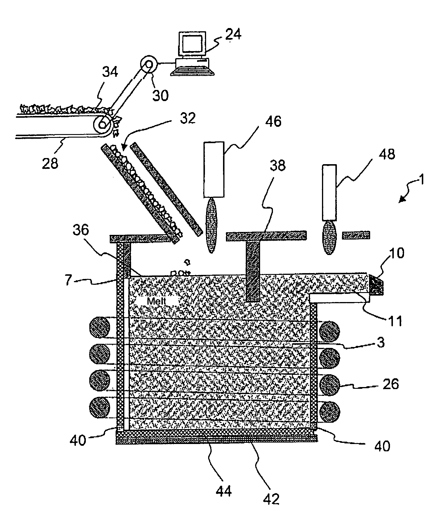
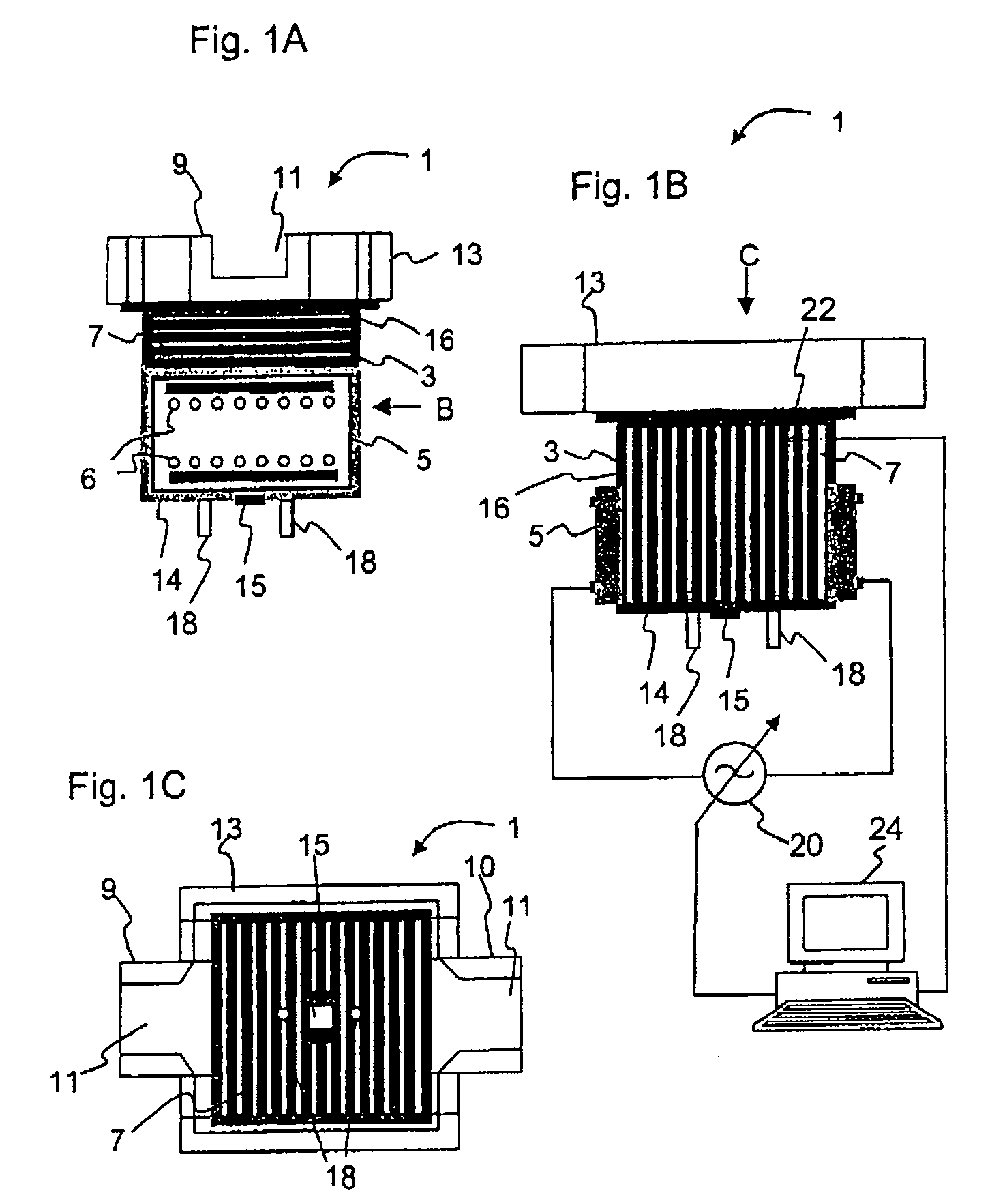
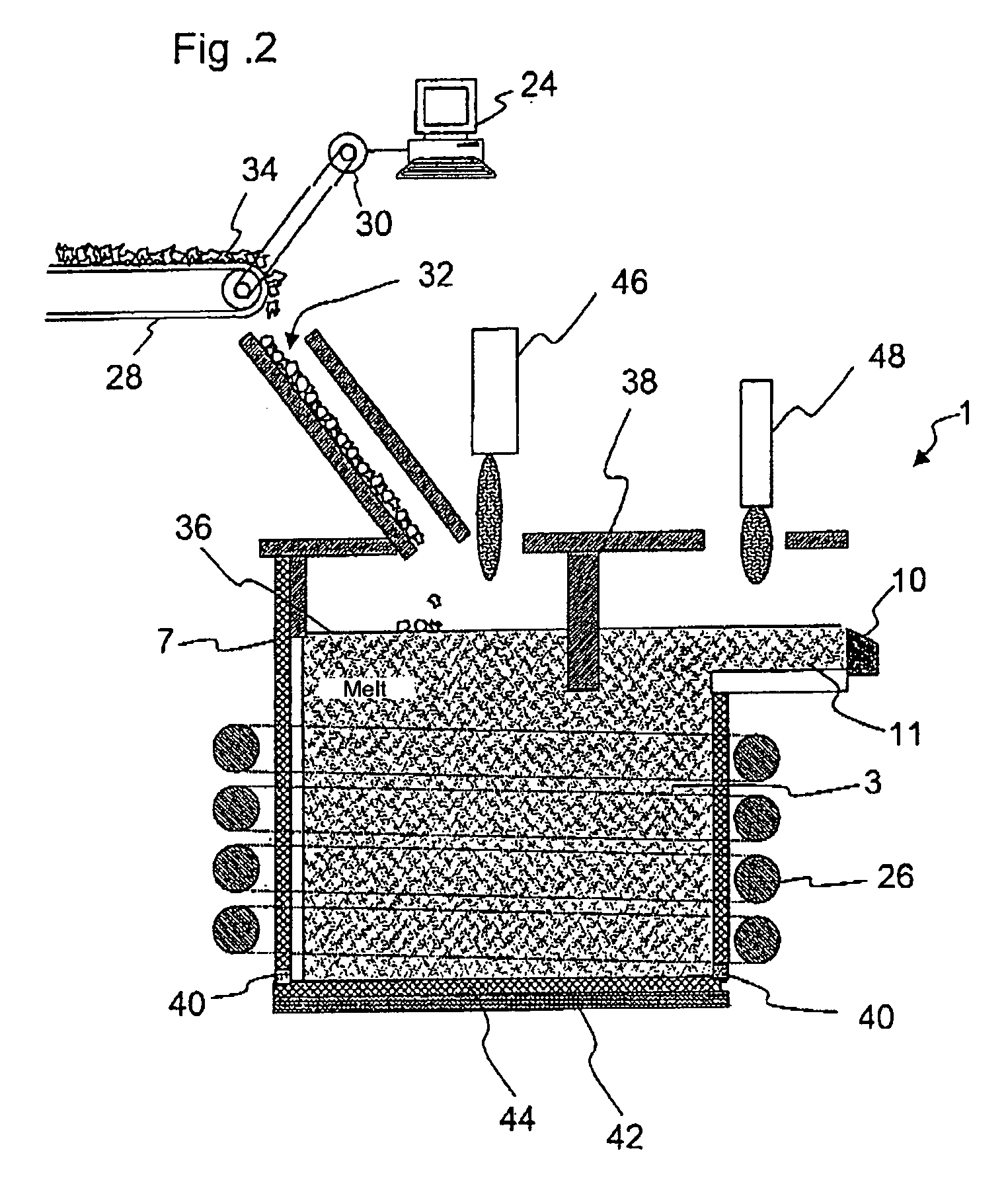
The patent is aimed at finding a way to use a melting unit with cooled walls while reducing the energy demand for every unit of molten material produced. The technical effect is to maintain the benefits of cooled walls melting, while reducing energy needs.

Problems solved by technology

However, melting in a melting unit with cooled walls, such as for example a skull crucible, has the drawback that the method is very energy-consuming, since the walls have to be very strongly cooled in order to cool the walls and / or produce a skull layer of the same type of material as the glass, and consequently a very large amount of energy is withdrawn from the glass melt.
This temperature difference increases at higher melting or refining temperatures, and consequently the energy loss through dissipation of heat is also increased at the same time.
Since both radiofrequency energy and fed-in conductive currents are expensive energy carriers, for example compared to fossil fuels, the abovementioned melting and refining methods have the reputation of being expensive and energy-consuming.
Furthermore, with conventional tanks, there may be problems with introducing the energy required to increase the temperature into the tank, since the higher burner temperature attacks the roof to a greater extent, and in the case of additional electrical heating the electrodes are extensively attacked.
An increased attack on the tank firstly shortens the service life of the tank and secondly has an adverse effect on the quality of glass.
Therefore, in conventional tanks, an increase in the throughput always entails the risk of a deterioration in the glass quality as a result of melting relics.
This is associated with increased production of environmentally harmful nitrogen oxides, NOx, in the atmosphere.
Consequently, with conventional tanks there are very tight limits on increasing the throughput by increasing the temperature, and consequently it is not appropriate to do so from an energy perspective.
Furthermore, the energy loss as the temperature increases rises to a greater extent with a skull crucible than with conventional tanks, as explained above.
This significantly higher energy loss from the melting units with cooled walls compared to the conventional tanks is the reason for melting in units with cooled walls, such as for example melting in skull crucibles, being relatively uncommon.
Despite having considerable advantages over conventional tanks, the skull melting method has hitherto only been used where conventional melting methods have failed.

Method used


Image

  • Melting and refining in tanks with cooled walls
  • Melting and refining in tanks with cooled walls
  • Melting and refining in tanks with cooled walls

Examples


example 1

Energy Saving when Refining

[0208]The increase in the melting temperature both shifts the thermodynamic equilibrium and lowers the viscosity. The lowering of the viscosity leads to an increase in the rate at which the bubbles rise up and an increase in the diffusion rate of the gases in the melt.

[0209]By way of example, in the case of an Li2O—Al2O3—SiO2 glass-ceramic melt, it has been experimentally determined that increasing the temperature from 1700° C. to 1900° C. allows the throughput in a refining unit to be increased by at least a factor of 5 without any loss of quality.

[0210]The increase in temperature lowers the viscosity of the melt, and as a result increases the rate at which the bubbles rise up, by a factor of 5.

[0211]Furthermore, in the case of Redox refining, an O2 overpressure is built up in the event of a rapid increase in temperature in the melt, and this O2 overpressure is only gradually reduced again through the formation of bubbles and discharge of bubbles at low m...

example 2

Test for Determining Teff

[0237]As has already been explained above, the energy consumption Etot, i.e. the sum of energy loss per unit weight EV through the walls and the base and the useful heat per unit weight EN for heating the melt, passes through a minimum at Teff, provided that the throughput is suitably adapted to the required residence time t.

[0238]The temperature Teff for the refining is estimated for a 700 liter skull crucible.

[0239]The calculation of the energy loss through the walls and the base as a function of the temperature is carried out with the aid of the diagram illustrated in FIG. 4.

[0240]The required residence time of the melt in the melting vessel or the increase in throughput as a function of temperature can be estimated in a first approximation on the basis of the increase in the rate at which the bubbles rise up. The rate at which the bubbles rise up v is calculated in accordance with the formula:

v=2 / 9*ρ*g*r2*1 / η

(V=rate at which the bubbles rise up; ρ=densi...

example 3

Melting Down with a Constant Melt Volume

[0251]In a similar way to in the case of refining, the residence time of the melt in the melting unit when melting down batch can also be significantly reduced as the temperature rises, and consequently the throughput can be increased.

[0252]When melting down batch, Teff can once again be determined by means of the holding time t of the glass melt in the melting unit.

[0253]To determine the temperature dependency of the residence time t, FIG. 8 plots the Ln of the reaction rate k for the dissolution of SiO2 against 1 / T*1000 (in degrees Kelvin, ° K) of the melt. The activation energy for melting down the batch can be estimated from FIG. 8 since the SiO2 is among the slowest of the constituents of the batch of the material to be melted to dissolve. It can be seen from FIG. 8 that the dissolution rate of the batch increases exponentially with the temperature. The rate at which SiO2 melts increases by approximately a factor of 3 per 100 K. These val...


PUM

PropertyMeasurementUnit
melt temperatureaaaaaaaaaa
temperatureaaaaaaaaaa

Abstract

A method for melting inorganic materials, preferably glasses and glass-ceramics, in a melting unit with cooled walls is provided. The method includes selecting the temperature of at least one region of the melt is selected in such a way as to be in a range from Teff−20% to Teff+20%, where the temperature Teff is given by the temperature at which the energy consumption per unit weight of the material to be melted is at a minimum, with the throughput having been selected in such a way as to be suitably adapted to the required residence time.

Description

CROSS-REFERENCE TO RELATED APPLICATIONS[0001]This application claims the benefit under 35 U.S.C. §365 of International Application No. PCT / EP2004 / 003416, filed Mar. 31, 2004, the entire contents of which are incorporated by reference herein.BACKGROUND OF THE INVENTION[0002]1. Field of the Invention[0003]The invention relates to a method and an apparatus for melting and / or refining, in particular in melting or refining units with cooled walls.[0004]It is an object of the invention to provide a method and an apparatus with reduced energy consumption when melting and / or refining inorganic substances, preferably glasses, glass-ceramics and crystals. The invention is preferably to be used in a melting or refining unit with cooled walls, for example in a skull crucible or a conductively heated tank.[0005]2. Description of Related Art[0006]The prior art has described a range of melting units with cooled walls, in particular skull crucibles, which are used to melt glasses using radiofrequen...

Claims


Application Information

Patent Timeline
Patent Type & Authority Patents(United States)
IPC IPC(8): C03B18/18C03B5/02C03B5/03C03B5/193C03B5/24
CPCC03B5/021C03B5/03C03B5/193C03B5/24Y02P40/57
Inventor KIEFER, WERNERROMER, HILDEGARDLENTES, FRANK-THOMASRAKE, GUIDOOHMSTEDE, VOLKERNAUMANN, KARINLEISTER, MICHAELNUESSLE, GERHARDRODEK, ERICHSCHMIDBAUER, WOLFGANG
Owner SCHOTT AG
Learn More