
Co-access bipolar ablation probe

a bipolar ablation and co-access technology, applied in the field of radio frequency (rf) ablation probes, can solve the problems of tumors that cannot be efficiently ablated using a standard bipolar ablation probe, pain in burns, tissue trauma, etc., and achieve the effect of improving the ablation process

Active Publication Date: 2013-04-09
BOSTON SCI SCIMED INC
View PDF22 Cites 9 Cited by
  • Summary
  • Abstract
  • Description
  • Claims
  • Application Information

AI Technical Summary

Benefits of technology

[0014]The method further comprises conveying ablation energy between the first and second electrodes located on the respective cannula and ablation probe to ablate the abnormal tissue. In the preferred method, the distance between the first and second electrodes is adjusted by sliding the ablation probe relative to the delivery cannula. In this case, the ablation energy is conveyed between the first and second electrodes while the first and second electrodes are maintained from each other at the adjusted distance. Optionally, the abnormal tissue is cooled during the tissue ablation to provide for a more efficient ablation process.

Problems solved by technology

Additionally, bipolar arrangements are generally safer for the physician and patient, since there is an ever-present danger that the physician and patient may become a ground in the monopolar arrangement, resulting in painful burns.
For example, even though such treatments can be considered minimally invasive in that open surgery is not required, they still require multiple instrument insertions during the biopsy, ablation, and drug delivery steps-causing tissue trauma with each insertion.
As such, some tumors may not be efficiently ablated using a standard bipolar ablation probe.

Method used


Image

  • Co-access bipolar ablation probe
  • Co-access bipolar ablation probe
  • Co-access bipolar ablation probe

Examples


Embodiment Construction

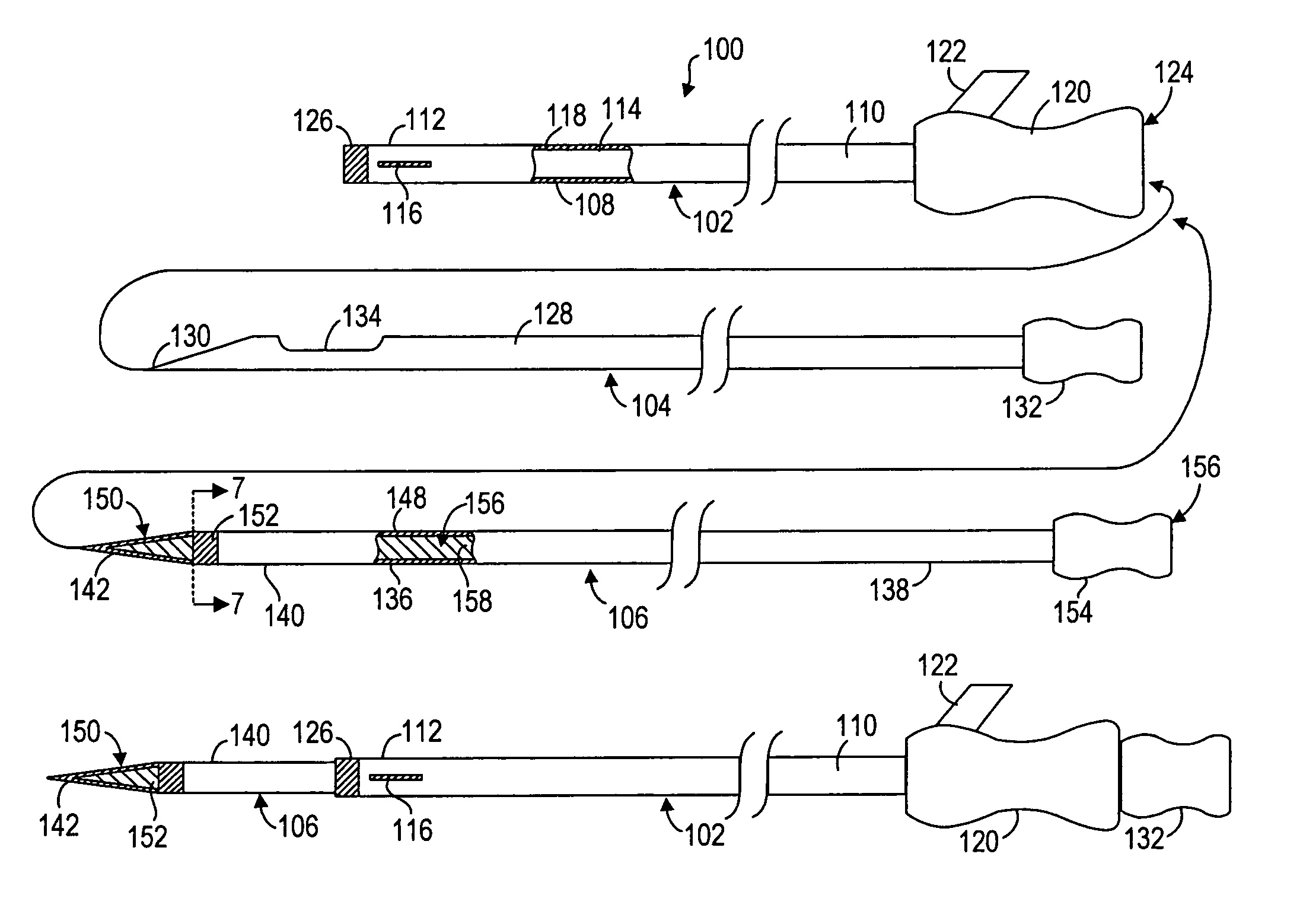
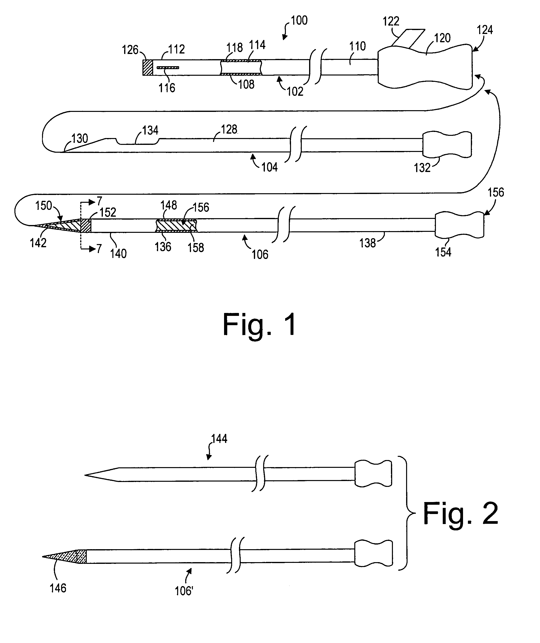
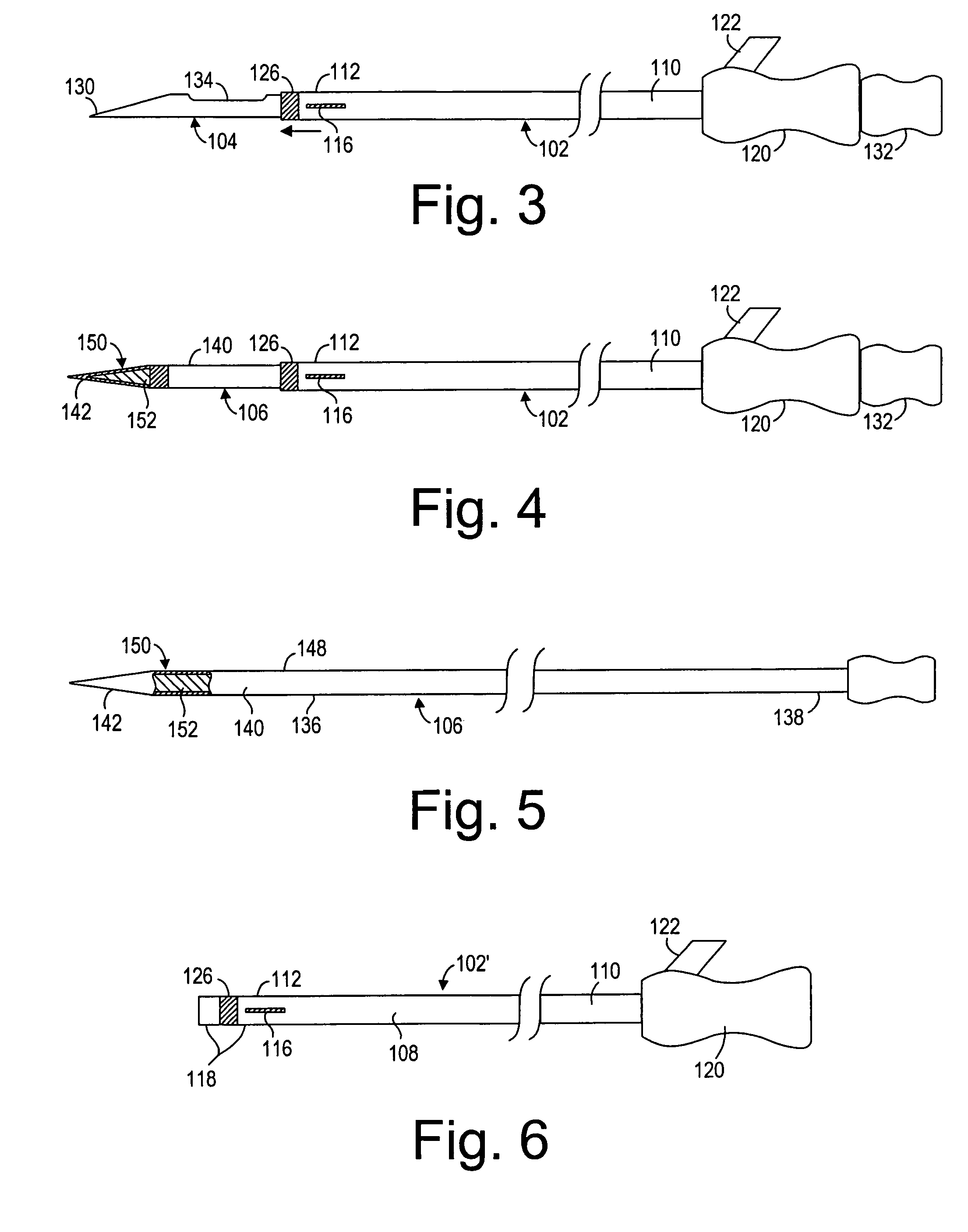
[0026]FIG. 1 illustrates a tissue treatment kit 100 arranged in accordance with a preferred embodiment of the present invention. The tissue treatment kit 100 generally comprises a delivery cannula 102 that can be percutaneously introduced within a patient, a biopsy stylet 104 configured for removing a tissue sample from the patient, and an ablation probe 106 configured for therapeutically ablating tissue. The biopsy stylet 104 and ablation probe 106 are configured to be alternately introduced through the delivery cannula 102 in contact with the tissue to be treated.

[0027]The delivery cannula 102 comprises a cannula shaft 108 having a proximal end 110 and a distal end 112, and a delivery lumen 114 extending through the cannula shaft 108. As will be described in further detail below, the cannula shaft 108 may be rigid, semi-rigid, or flexible, depending upon the designed means for introducing the delivery cannula 102 to the target tissue. The distal end 112 of the cannula shaft 108 pr...


PUM


Abstract

A medical probe kit and method of treating abnormal tissue within a patient is provided. The kit comprises a cannula having a shaft, a lumen extending through the cannula shaft, and a first ablation electrode disposed on the distal end of the cannula shaft. The cannula may have a handle mounted to the proximal end of the cannula shaft, and an optional fluid delivery port on the handle in fluid communication with the cannula lumen. The kit further comprises an ablation probe configured to be removably disposed within the delivery cannula lumen. The ablation probe has a shaft and a second ablation electrode disposed on a distal end of the probe shaft, wherein the first and second ablation electrodes are arranged in a bipolar configuration. Preferably, the ablation probe is slidable relative to the delivery cannula, whereby the distance between the first and second ablation electrodes can be adjusted. Thus, the delivery cannula can be used to interchangeably deliver the ablation probe and other medical elements, such as a biopsy needle, obturator, and chemotherapeutic agent.

Description

FIELD OF THE INVENTION[0001]The field of the invention relates generally to the structure and use of radio frequency (RF) ablation probes for the treatment of tissue.BACKGROUND OF THE INVENTION[0002]The delivery of radio frequency (RF) energy to target regions within solid tissue is known for a variety of purposes of particular interest to the present invention. In one particular application, RF energy may be delivered to diseased regions (e.g., tumors) for the purpose of ablating predictable volumes of tissue with minimal patient trauma.[0003]In a typical procedure, tissue suspected of containing an abnormality is imaged using a high definition imaging modality, such as Magnetic Resonance Imaging (MRI). If an abnormality, such as a tumor, is discovered, a sample of the abnormal tissue is retrieved. This is typically accomplished by percutaneously introducing a biopsy needle through healthy tissue into contact with the abnormal tissue. Proper guidance and placement of the biopsy nee...

Claims


Application Information

Patent Timeline
Patent Type & Authority Patents(United States)
IPC IPC(8): A61B18/18A61B10/02A61B18/00A61B18/14
CPCA61B18/1477A61B18/00A61B10/0275A61B2018/00005A61B2018/00047A61B2018/143
Inventor RIOUX, ROBERT F.DICARLO, PAULANDERSON, STEVE
Owner BOSTON SCI SCIMED INC
Learn More