Faucet with retractable spout that can be positioned quickly and automatically

a faucet and spout technology, applied in mechanical equipment, transportation and packaging, valve types, etc., can solve the problem of inconvenient operation of the faucet by users

Active Publication Date: 2013-04-09
CHUNG CHENG FAUCET
View PDF5 Cites 53 Cited by
  • Summary
  • Abstract
  • Description
  • Claims
  • Application Information

AI Technical Summary

Benefits of technology

[0007]According to the primary advantage of the present invention, when the locking sleeve is inserted into the receiving space of the elastic sleeve, the second magnetic member is attracted magnetically by the first magnetic member so as to position the locking sleeve in the receiving space of the elastic sleeve and to position the spout onto the distal end of the bent tube so that the spout is positioned onto the distal end of the bent tube automatically.
[0008]According to another advantage of the present invention, the second magnetic member is attracted magnetically by the first magnetic member, and the boss of the spout is inserted into the depression of the protrusion so that the spout is positioned onto the distal end of the bent tube solidly and stably without producing a gap between the spout and the distal end of the bent tube to prevent the spout from being vibrated or swayed during a normal operation.
[0009]Further benefits and advantages of the present invention will become apparent after a careful reading of the detailed description with appropriate reference to the accompanying drawings.BRIEF DESCRIPTION OF THE SEVERAL VIEWS OF THE DRAWING(S)
[0010]FIG. 1 is a perspective view of a faucet in accordance with the preferred embodiment of the present invention.
[0011]FIG. 2 is an exploded perspective view of the faucet as shown in FIG. 1.
[0012]FIG. 3 is a partially exploded perspective view of the faucet as shown in FIG. 1.

Problems solved by technology

However, the spout assembly is fixed on the faucet body so that the spout assembly cannot be moved freely to satisfy the user requirement, thereby causing inconvenience to the user when operating the faucet.

Method used


Image

  • Faucet with retractable spout that can be positioned quickly and automatically
  • Faucet with retractable spout that can be positioned quickly and automatically
  • Faucet with retractable spout that can be positioned quickly and automatically

Examples


Embodiment Construction

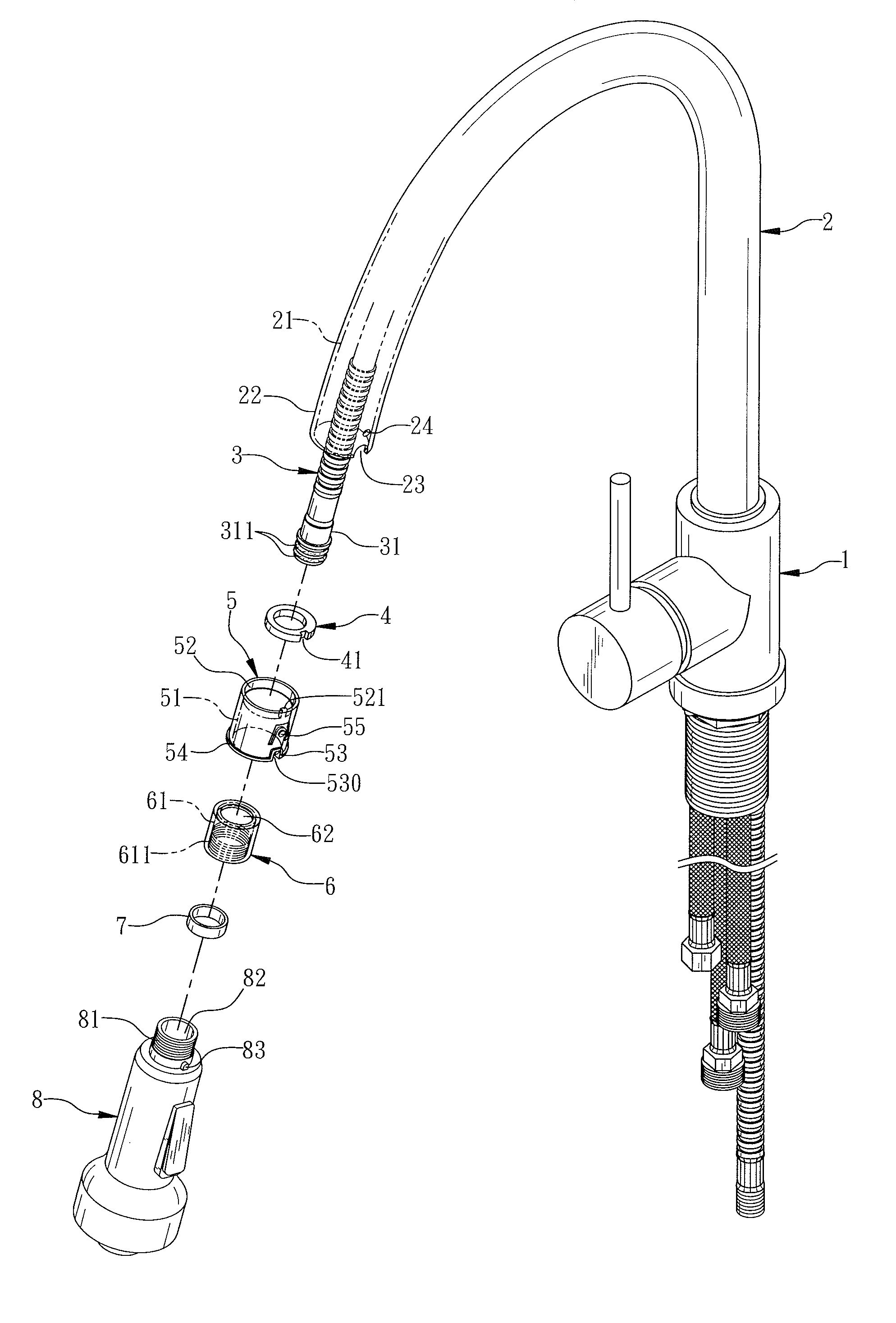
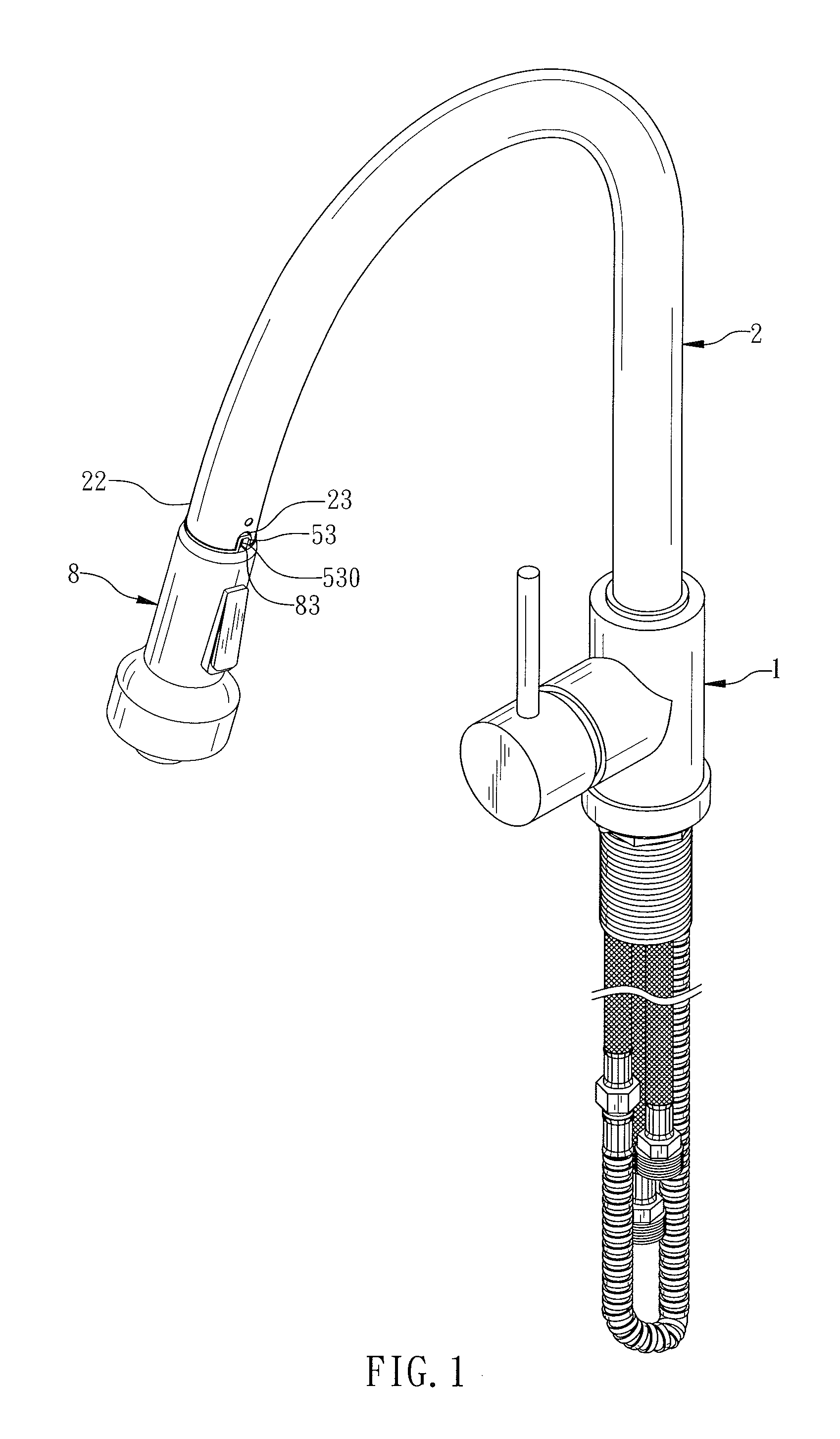
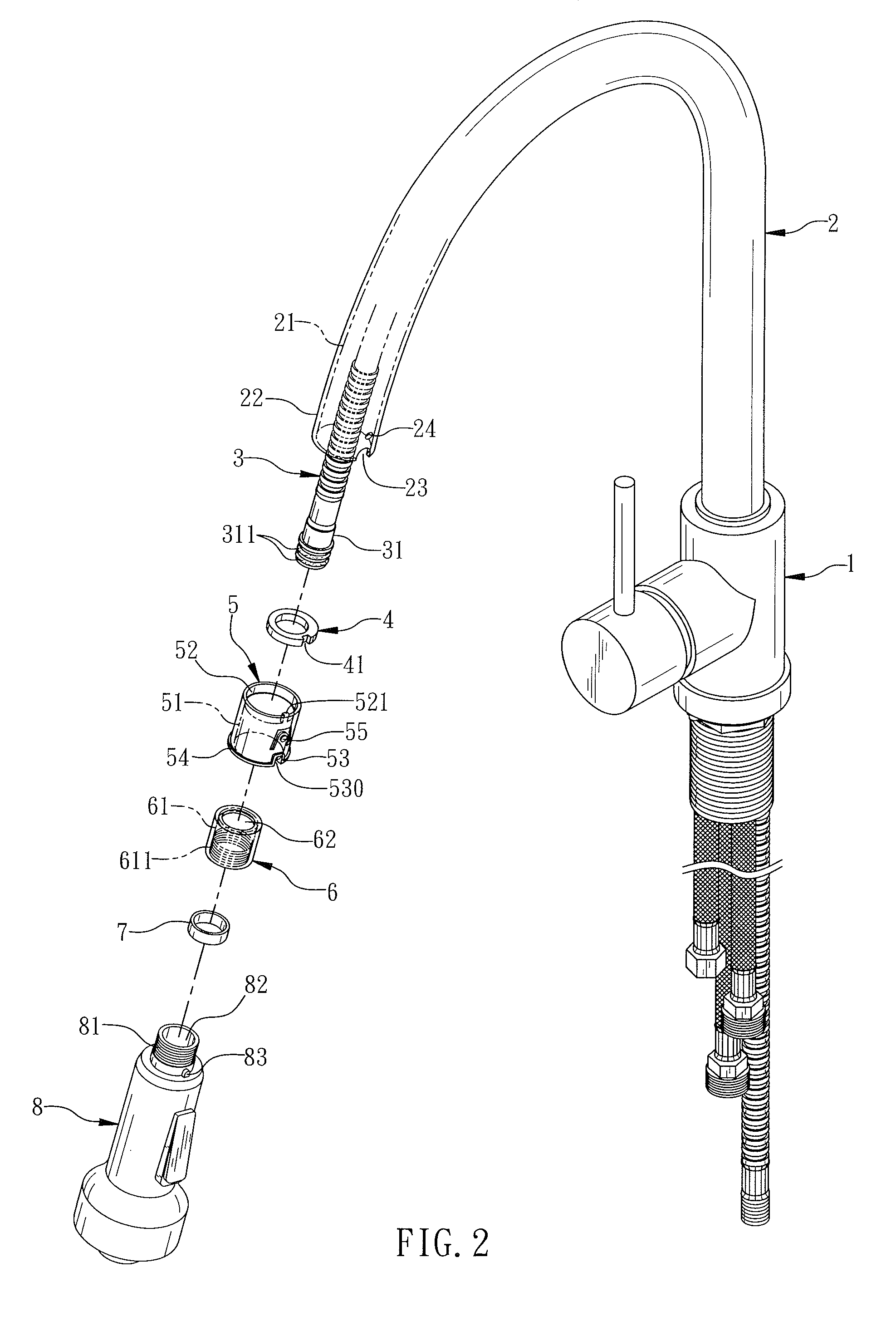
[0015]Referring to the drawings and initially to FIGS. 1-4, a faucet in accordance with the preferred embodiment of the present invention comprises a faucet body 1, a bent tube 2 mounted on the faucet body 1, a flexible water outlet pipe 3 retractably mounted in the bent tube 2 and having a distal end provided with a connector 31 protruding outwardly from a distal end 22 of the bent tube 2, an elastic sleeve 5 mounted in the distal end 22 of the bent tube 2, a first magnetic member 4 mounted in the elastic sleeve 5, a locking sleeve 6 mounted on the connector 31 of the water outlet pipe 3 and detachably inserted into the elastic sleeve 5, a second magnetic member 7 mounted in the locking sleeve 6 to move in concert with the locking sleeve 6 and movable to approach the first magnetic member 4 so that the second magnetic member 7 is attracted magnetically by the first magnetic member 4 to attach the locking sleeve 6 to the elastic sleeve 5, and a spout 8 locked onto the locking sleeve...


PUM


Abstract

A faucet includes a faucet body, a bent tube mounted on the faucet body, a water outlet pipe retractably mounted in the bent tube and having a connector, an elastic sleeve mounted in the distal end of the bent tube, a first magnetic member mounted in the elastic sleeve, a locking sleeve mounted on the connector of the water outlet pipe and inserted into the elastic sleeve, a second magnetic member mounted in the locking sleeve and movable to approach the first magnetic member, and a spout locked onto the locking sleeve. Thus, when the locking sleeve is inserted into the elastic sleeve, the second magnetic member is attracted magnetically by the first magnetic member so as to position the locking sleeve in the elastic sleeve and to position the spout onto the distal end of the bent tube.

Description

BACKGROUND OF THE INVENTION[0001]1. Field of the Invention[0002]The present invention relates to a water output device and, more particularly, to a water faucet for spraying water outward.[0003]2. Description of the Related Art[0004]A conventional faucet comprises a faucet body, a water inlet pipe connected with the faucet body, a spout assembly mounted on the faucet body, and a control lever mounted on the faucet body. Thus, by control of the control lever, the water from the water inlet pipe is delivered through the faucet body to the spout assembly and is injected outward from the spout assembly for use with a user. However, the spout assembly is fixed on the faucet body so that the spout assembly cannot be moved freely to satisfy the user requirement, thereby causing inconvenience to the user when operating the faucet.BRIEF SUMMARY OF THE INVENTION[0005]In accordance with the present invention, there is provided a faucet, comprising a faucet body, a bent tube mounted on the fauc...

Claims


Application Information

Patent Timeline
Patent Type & Authority Patents(United States)
IPC IPC(8): B05B7/02
CPCE03C1/0404E03C2001/0415Y10T137/9464
Inventor KO, JUI-FENG
Owner CHUNG CHENG FAUCET
Why Eureka
Try Eureka