Cooling device including a water-absorbing member and image forming device

a cooling device and water-absorbing member technology, applied in electrographic process devices, lighting and heating devices, instruments, etc., can solve the problems of affecting the subsequent image forming, affecting the cooling liquid, so as to prevent a contaminant and prevent an increase in size

Inactive Publication Date: 2013-04-02
RICOH KK
View PDF14 Cites 0 Cited by
  • Summary
  • Abstract
  • Description
  • Claims
  • Application Information

AI Technical Summary

Benefits of technology

[0010]In light of what is described in the above, the present invention seeks to provide a cooling device which makes it possible to maintain a state of connecting between a moving cooling unit such as a cooling pipe, etc., and a cooling medium supplying unit such as the circulation pipe, and an image forming device having the cooling device.
[0027]The present invention makes it possible to prevent a contaminant from finding its way into a flow channel since a cooling section and a cooling medium supply section may be left connected, regardless of whether the cooling section is arranged at a first location or a second location. In this way, degradation of a cooling medium and a possibility of failure of the cooling medium supply section, etc., may be prevented. Moreover, while a cooling liquid which remains in the connecting section (the separating section) of the cooling pipe drops into the image forming device when a cooling pipe is separated in the conventional cooling device, this is not the case here so that there is no possibility of causing a detrimental effect on image forming. Moreover, regardless of whether the cooling section is arranged at the first location or the second location, the cooling medium may be supplied to the cooling medium supply section, making it possible to continuously conduct cooling by the cooling section. Furthermore, the features of the present invention may be adopted to provide the cooling medium supply section in the image forming device body, making it possible to prevent an increase in size which arises as a result of integrally arranging the cooling medium supply section and the cooling section.

Problems solved by technology

However, in case of the image forming device disclosed in Patent document 1, pulling out the process unit separates a cooling pipe provided at the process unit and a circulation pump provided at the image forming device body, so that cooling is not conducted in such a state.
Therefore, when conducting maintenance, etc., it is likely that the process unit remains at high temperature, so that touching the process unit may be dangerous.
Moreover, a cooling liquid which remains at a connecting section (a separating section) dropping into the image forming device at the time of separating the cooling pipe and the circulation pipe may detrimentally affect subsequent image forming.
Furthermore, when a contaminant such as toner or paper powder that scatters within the device fixes to the cooling liquid which remains in the connecting section (separating section), the contaminant finds its way into the cooling device, possibly causing degradation of the cooling liquid, a failure of the circulation pump, etc.
On the other hand, while it is also possible to integrally arrange the circulation pump and the process unit so as to make it possible for the cooling liquid to circulate even when being pulled out, this leads to an increased size of the process unit, thus leading to reduced capabilities for maintenance and paper jamming processes.
Moreover, an increased sized process unit leads to the necessity of increasing the strength of a housing which supports the same, running counter to a goal of reduced size and weight.
Furthermore, the above problem may occur not only for the process unit, but similarly also for any fixing device and other devices requiring cooling.

Method used


Image

  • Cooling device including a water-absorbing member and image forming device
  • Cooling device including a water-absorbing member and image forming device
  • Cooling device including a water-absorbing member and image forming device

Examples


embodiment 1

[0083]FIGS. 6(a) and 6(b) are diagrams illustrating a configuration according to Embodiment 1 of the present invention. FIG. 6(a) is a lateral view of the heat receiving plate 31 being tucked in and FIG. 6(b) is a lateral view of the heat receiving plate 31 being pulled out. Moreover, in FIGS. 6(a) and 6(b), the fixing device 8, etc. are omitted.

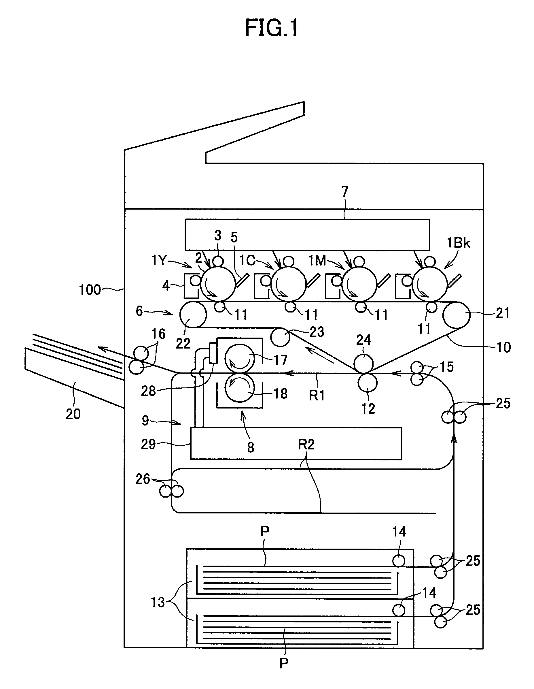
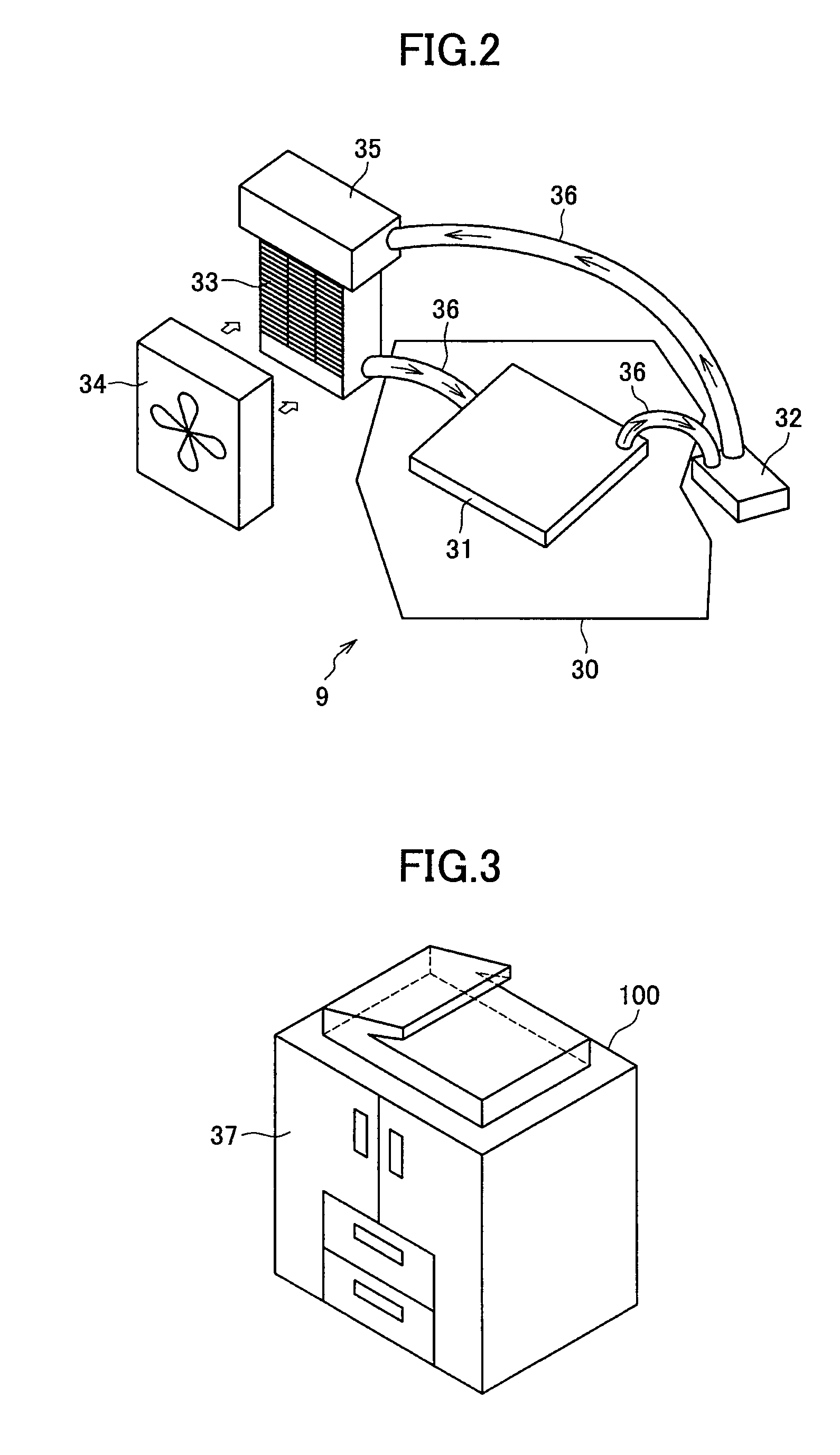
[0084]As illustrated in FIGS. 6(a) and 6(b), a supply tube 40 for supplying the cooling liquid into the heat receiving plate 31 and a discharge tube 41 for discharging the cooling liquid from the heat receiving plate 31 are connected to the heat receiving plate 31. The supply tube 40 and the discharge tube 41 are flow channels which make up a part of the circulation routes 36 as shown in FIG. 2. More specifically, a connecting member which connects the heat receiving plate 31 and the radiator 33 is the supply tube 40, while a connecting member which connects the heat receiving plate 31 and the pump 32 is the discharge tube 41. The supply tub...

embodiment 2

[0089]FIG. 7 is a diagram illustrating a configuration according to Embodiment 2 of the present invention with a lateral view of the heat receiving plate 31 being pulled out.

[0090]As shown in FIG. 7, in Embodiment 2, in a manner similar to Embodiment 1, an extending / contracting supporting unit 42 is provided which includes multiple arm members 42b oscillatably connected via the joint section 42a, the supply tube 40 and the discharge tube 41 being tucked in the arm members 42b. Moreover, in Embodiment 2, a joint section 42a of the extending / contracting supporting unit 42 is mounted to the sliding member 39 which supports the pulling out section 38 in such a manner that the pulling out section 38 can be pulled out and tucked in. More specifically, a joint section 42a which is arranged on the upper side out of multiple joint sections 42a alternately arranged in the upward and downward directions is mounted to the sliding member 39. In this way, the extending / contracting supporting unit...

embodiment 3

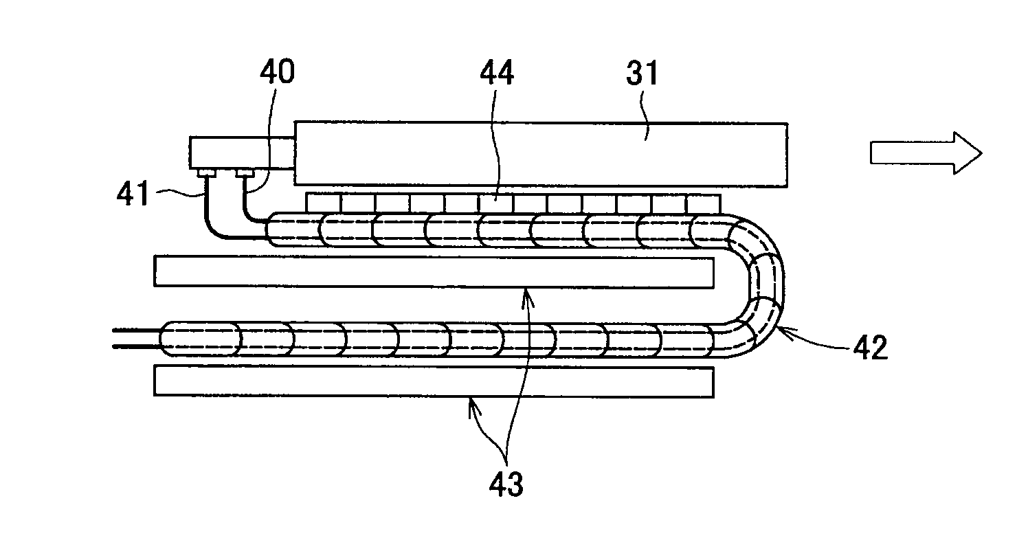
[0093]FIGS. 8 and 9 are diagrams illustrating configurations according to Embodiment 3 of the present invention. FIG. 8 is a lateral view of the heat receiving plate 31 being pulled out, while FIG. 9 is a top view of the heat receiving plate 31 being pulled out. In FIGS. 8 and 9, the fixing device 8, which is provided at the pulling out section 38, is omitted.

[0094]As shown in FIG. 8 or FIG. 9, in Embodiment 3, as in Embodiment 1, there is provided an extending / contracting supporting unit 42 which includes multiple arm members 42b, which are oscillatably connected via the joint section 42a. Moreover, as shown in FIG. 9, the supply tube 40 and the discharge tube 41 are carried within the arm member 42b. In Embodiment 3, unlike the previously-described Embodiments, the arm members 42b are arranged such that they bend laterally in a zigzag manner. Moreover, the arm member 42b is arranged such that it contacts a bottom plate 43 which is arranged at the image forming device body 100. In ...


PUM


Abstract

A cooling device is disclosed. The cooling device includes a cooling section which is moveably provided with respect to an image forming device body between a first location and a second location, the second location being different from the first location, and which cools surroundings with a cooling medium to be supplied; a cooling medium supply section which is provided at the image forming device body and which cools the cooling medium to supply the cooled cooling medium to the cooling section; and a connecting member which connects the cooling section and the cooling medium supply section to circulate the cooling medium between the cooling section and the cooling medium supply section, wherein the connecting member includes a flexible member and is supported by a guiding member which guides an operation of tracking the connecting member in conjunction with movement of the cooling section.

Description

TECHNICAL FIELD[0001]The present invention relates to a cooling device having a cooling section which is provided movably with respect to the body of an image forming device, and the image forming device provided with the cooling device.BACKGROUND ART[0002]There is an image forming device such as a copier, a printer, a facsimile machine, or a multi-functional unit having these functions, which is provided with a cooling device for cooling a device provided around a device which liberates heat (e.g., a fixing device). For example, Patent document 1 discloses an image forming device provided with a liquid-cooling type cooling device for cooling a process unit that is removable with respect to the body of the image forming device.[0003]Moreover, in recent years, for the purpose of improving printing speed, amount of heat provided to paper at the time of image fixing is increasing, so that paper curling as well as a phenomenon, so-called blocking, in which softened toner sticks to a dif...

Claims


Application Information

Patent Timeline
Patent Type & Authority Patents(United States)
IPC IPC(8): G03G21/20
CPCG03G21/20F28D15/00F28D2021/0031
Inventor NISHIMURA, TAKAYUKITAKEHARA, KENICHIIIJIMA, YASUAKIFUJIYA, HIROMITSUOKANO, SATOSHIHIRASAWA, TOMOYASUSAITOH, MASANORISUZUKI, SHINGOOGINO, TAKAHIRO
Owner RICOH KK
Why Eureka
Try Eureka