Control device for vehicle

Active Publication Date: 2020-10-01
TOYOTA JIDOSHA KK
View PDF0 Cites 0 Cited by
  • Summary
  • Abstract
  • Description
  • Claims
  • Application Information

AI Technical Summary

Benefits of technology

The invention relates to a control device for vehicles that prevents unintended shifting during power interruptions. The control device includes a shift-switching control portion that learns the initial position of the actuator when the power source is interrupted. This allows the actuator to switch to the desired position without being affected by the power interruption. Additionally, the invention includes a method for initial position learning that ensures the reference position is set properly. This approach eliminates the need for storage space in the control device and reduces costs.

Problems solved by technology

This may cause switching to a shift position unintended by a driver of the vehicle.

Method used


Image

  • Control device for vehicle
  • Control device for vehicle
  • Control device for vehicle

Examples


example 1

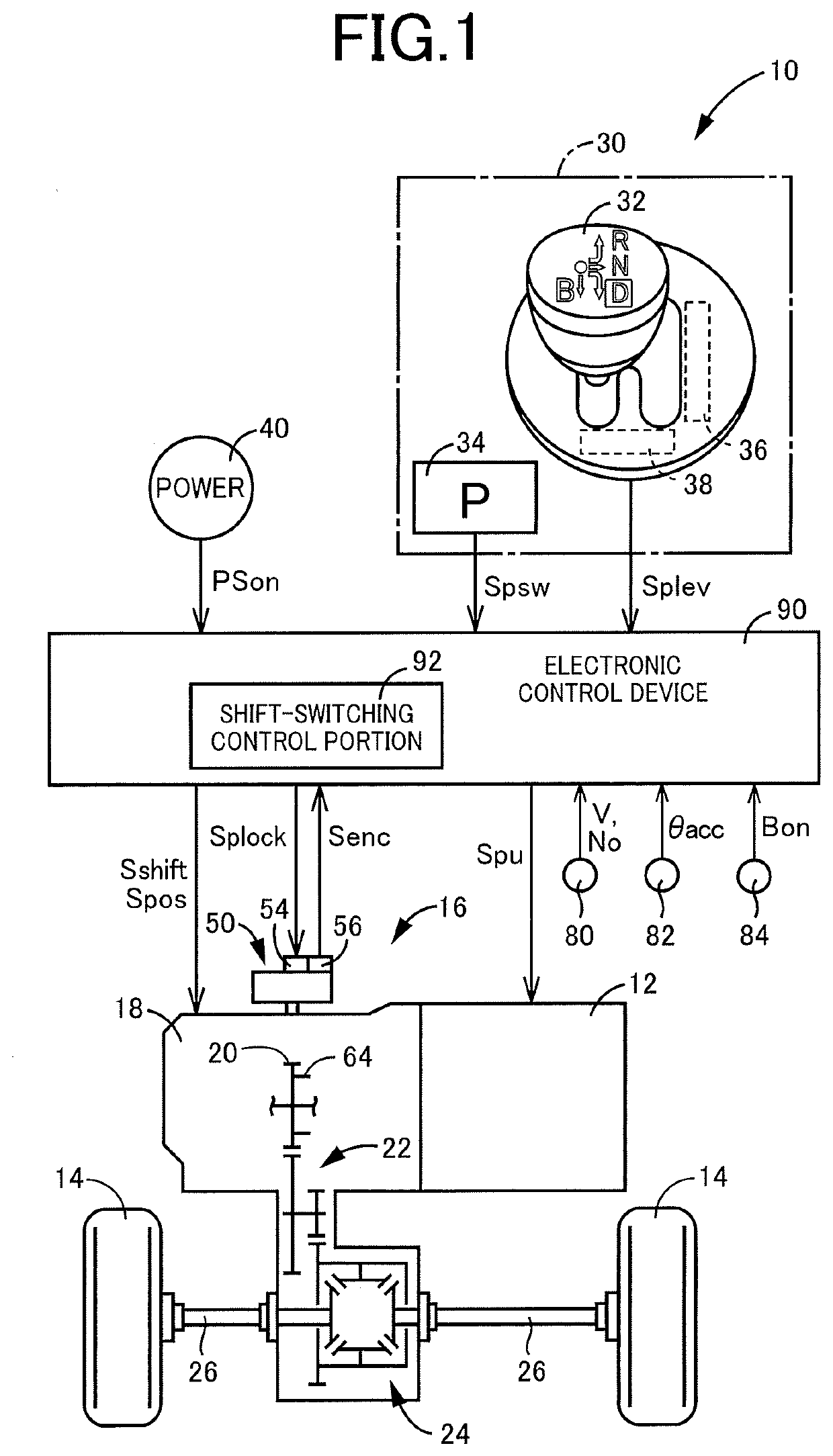
[0026]FIG. 1 is a diagram showing a schematic configuration of a vehicle 10 to which the present invention is applied. FIG. 1 is also a diagram for explaining main portions of control functions and control systems for various controls in the vehicle 10. In FIG. 1, the vehicle 10 includes a drive power source 12, drive wheels 14, and a power transmission device 16 for transmitting a power of the drive power source 12 to the drive wheels 14.

[0027]The power transmission device 16 includes an automatic transmission 18 coupled to the drive power source 12, a reduction gear mechanism 22 coupled to an output gear 20 that is an output rotating member of the automatic transmission 18, a differential gear 24 coupled to the reduction gear mechanism 22, and left and right drive shafts 26 coupled to the differential gear 24. In the power transmission device 16, the power output from the drive power source 12 is transmitted sequentially through the automatic transmission 18, the reduction gear me...

example 2

[0077]During stop of the vehicle, the P ratcheting due to switching to the P position during running does not occur. Therefore, the shift-switching control portion 92 may be configured to not perform the initial position learning process of the motor 54 until the shift switching operation is performed by the driver only when the momentary interruption of the ECU power source has occurred during running.

[0078]FIG. 7 is a flowchart for explaining a main portion of control actuation of the electronic control device 90, i.e., control actuation for avoiding the switching to a shift position unintended by the driver at the time of occurrence of the momentary interruption of the ECU power source, and is repeatedly executed. The flowchart of FIG. 7 is an example different from the flowchart of FIG. 5. Steps in the flowchart of FIG. 7 correspond to the function of the shift-switching control portion 92.

[0079]In FIG. 7, first, at S15, it is determined whether the ECU power source is reset due...


PUM


Abstract

A control device for a vehicle including (i) a power transmission device, (ii) a shift operation device that is to be operated by a driver of the vehicle to an operation position corresponding to a shift position of the power transmission device, and (iii) a switching device for switching the shift position of the power transmission device through actuation of an actuator. The control device is configured, upon occurrence of a momentary interruption of a control-device electric-power source that is supplied with an electric power from a vehicle electric-power source, to not perform an initial position learning process for setting a reference position of the actuator, until a shift switching operation for switching the shift position of the power transmission device is performed by a driver of the vehicle.

Description

This application claims priority from Japanese Patent Application No. 2019-070252 filed on Apr. 1, 2019, the disclosure of which is herein incorporated by reference in its entirety.FIELD OF THE INVENTION[0001]The present invention relates to a control device for a vehicle, which is for switching a shift position of a power transmission device based on a control command signal corresponding to an operation position of a shift operation device.DESCRIPTION OF THE RELATED ART[0002]There is well known a control device for a vehicle including (i) a power transmission device configured to transmit a power of a drive power source to drive wheels of the vehicle, (ii) a shift operation device that is to be operated by a driver of the vehicle to an operation position corresponding to a shift position of the power transmission device, and (iii) a switching device configured to switch the shift position of the power transmission device through actuation of an actuator based on a control command ...

Claims


Application Information

Patent Timeline
IPC IPC(8): F16H59/08F16H61/18F16H61/32
CPCF16H2061/0087F16H61/18F16H61/32F16H59/08F16H2061/326F16H61/12F16H2061/1292F16H63/3433F16H59/10F16H2059/0295F16H59/0217F16H2061/1268F16H2061/1224F16H63/3458F16H63/3466
Inventor YAMAUCHI, YUSUKEUENO, KOKINAKADE, YUSUKEKITAORI, ICHIRO
Owner TOYOTA JIDOSHA KK
Why Eureka
Try Eureka