
Tomographic image reconstruction method and apparatus using filtered back projection

a reconstruction method and back projection technology, applied in the field of tomographic image reconstruction method, can solve the problems of long computation time incurred with iterative algebraic reconstruction method, short calculation time, and correspondingly high measurement and calculation cost, and achieve the effect of high flexibility in the determination of filter kernels

Active Publication Date: 2013-04-02
SIEMENS HEALTHCARE GMBH
View PDF12 Cites 9 Cited by
  • Summary
  • Abstract
  • Description
  • Claims
  • Application Information

AI Technical Summary

Benefits of technology

[0014]A high flexibility in the determination of a filter kernel optimized for the imaging or diagnostic task to be performed is possible through the determination of an analytical filter kernel that can be represented by a first analytical function. This analytical filter kernel is determined from a discrete filter kernel iteratively determined with an algebraic reconstruction method (meaning the approximation of the discrete filter kernel via a continuous function from which a second analytical filter kernel can be calculated by mathematical operations).

Problems solved by technology

The long computation times incurred with iterative algebraic reconstruction methods, however, are disadvantageous.
A significant problem in filtered back projection is the provision of suitable filters with which it is possible for the physical measurement method that is used and the geometry that is used (for example conventional CT or tomosynthesis with limited angle range) to generate tomographic images with high clarity in order to differentiate benign from malignant variations and in order to be able to reduce the number of incorrect findings, i.e. the number of the suspected findings that are caused by non-malignant variations and the number of undetected malignant tumors.
The desired image quality therefore results in a short calculation time.
Such an optimization would require the use of a number of such discrete filter kernels calculated via iterative, algebraic reconstruction, with correspondingly high measurement and calculation cost.

Method used


Image

  • Tomographic image reconstruction method and apparatus using filtered back projection
  • Tomographic image reconstruction method and apparatus using filtered back projection
  • Tomographic image reconstruction method and apparatus using filtered back projection

Examples


Embodiment Construction

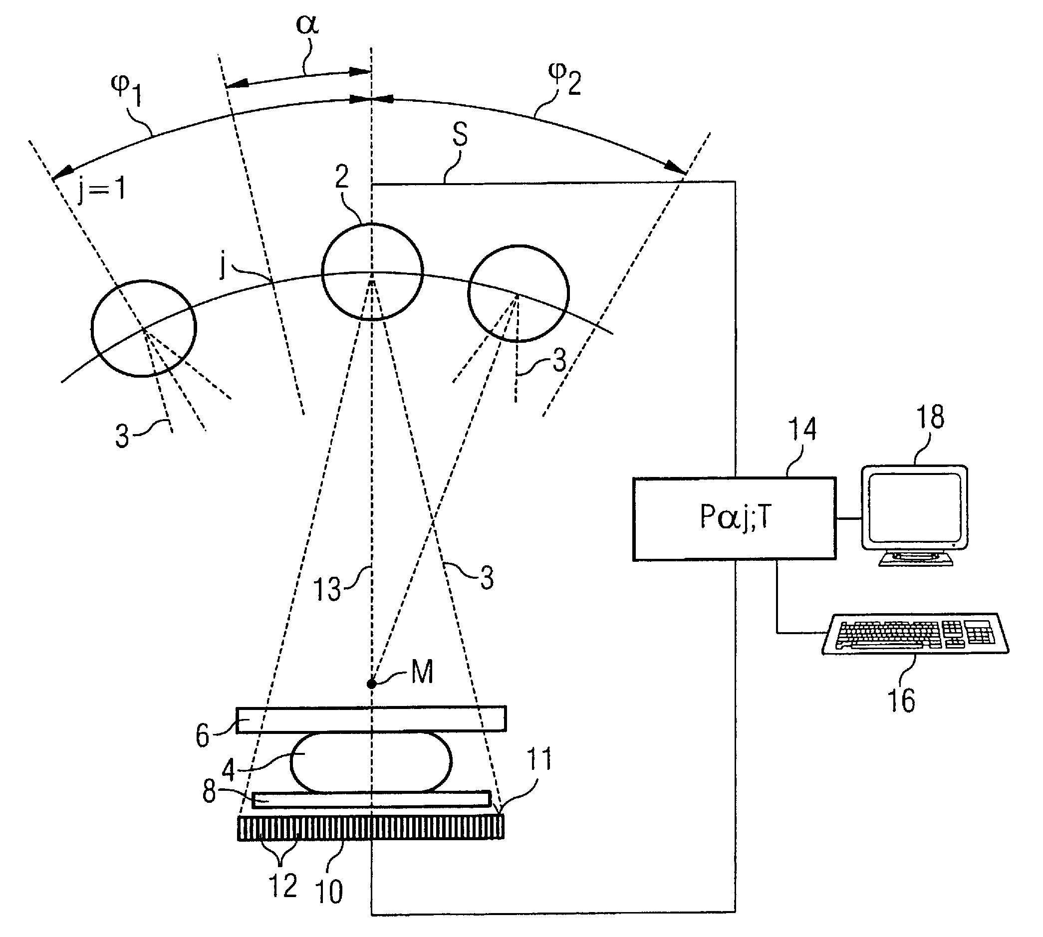
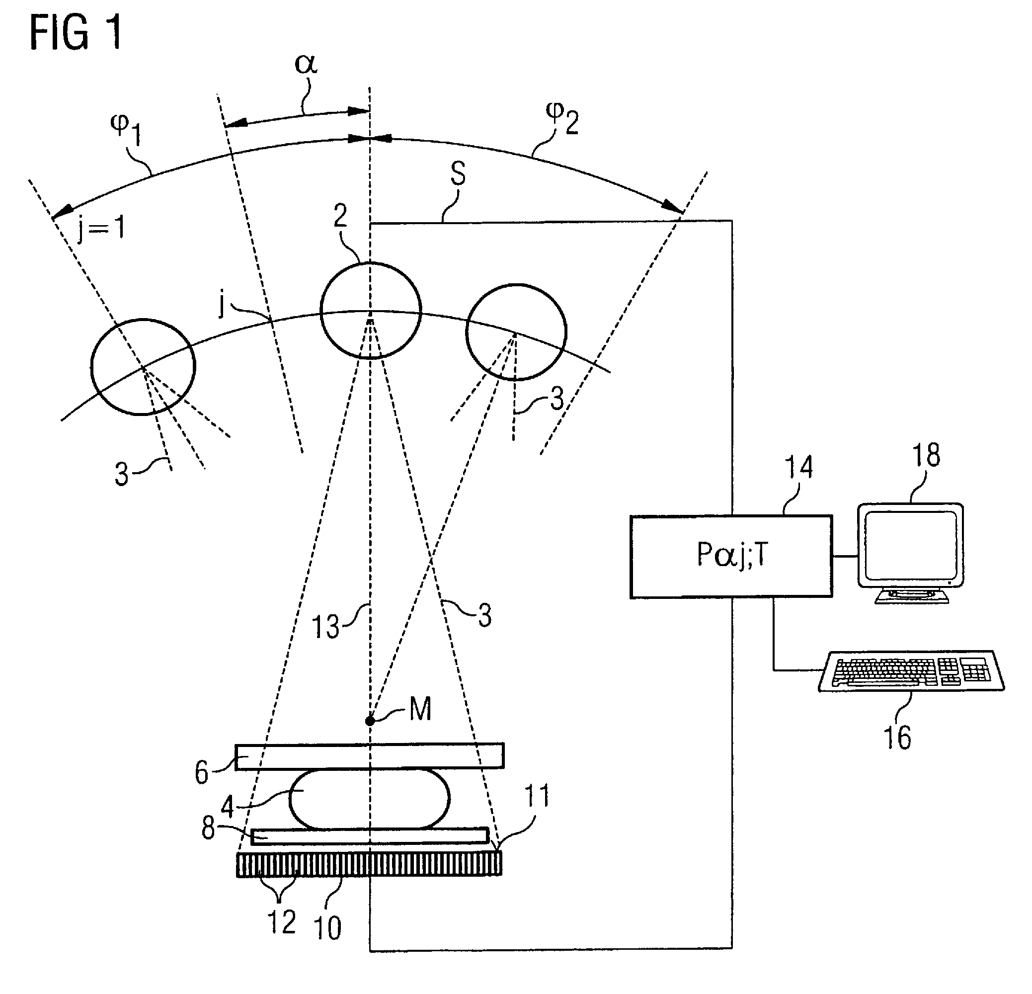
[0021]As shown in FIG. 1, the imaging device (in the exemplary embodiment a mammography apparatus provided for the generation of tomosynthetic images) has an x-ray tube 2 for the generation of x-rays 3 that penetrate an examination subject 4. The examination subject 4 is a female breast that is held between a compression plate 6 and a support plate 8. The x-rays 3 penetrating the examination subject 4, the compression plate 6 and the support plate 8 are received by a large-surface digital x-ray detector 10 that is constructed of a number of individual detectors 12 arranged in a matrix-like array, and whose acquisition surface 11 is arranged parallel to the plates 6, 8.

[0022]The x-ray tube 2 is mounted such that its location can be adjusted in a limited range relative to the examination subject, and can for example be pivoted into different angle positions j=1 . . . n in a limited angle range φ1, φ2 on an axis M perpendicular to the plane of the drawing. Individual images of the exam...


PUM


Abstract

In a tomographical image reconstruction method and apparatus to generate an image of an examination subject from a number of digital projection data acquired at different projection angles, a first analytical filter kernel (formed by a first analytical function) is determined for a filtered back projection in the spatial frequency range, this first analytical filter kernel approximating, at least in a range of the spatial frequency, a discrete filter kernel iteratively determined for a model. Back projection is implemented with a second analytical filter kernel calculated from the analytical filter kernel and formed by a second analytical function.

Description

BACKGROUND OF THE INVENTION[0001]1. Field of the Invention[0002]The present invention concerns a tomographical image reconstruction method for generation of an image of an examination subject. The present invention also concerns an imaging device operating according to such a method.[0003]2. Description of the Prior Art[0004]Tomographical image reconstruction is a computerized method that allows a two-dimensional image or a three-dimensional volume image of the examination subject to be generated from projection (two-dimensional) data acquired at different projection angles.[0005]For this purpose, a number of mathematical algorithms are known, among which include iterative, algebraic reconstruction methods that have proven to be particularly suitable for conventional computed tomography (CT) operating with x-ray radiation as well as for tomosynthesis (likewise operating with x-ray radiation).[0006]Tomosynthesis is an imaging method in which individual images or projection data of an...

Claims


Application Information

Patent Timeline
Patent Type & Authority Patents(United States)
IPC IPC(8): G06K9/00
CPCA61B6/502G06T11/006G06T2211/436
Inventor LUDWIG, JASMINAMERTELMEIER, THOMAS
Owner SIEMENS HEALTHCARE GMBH
Learn More