
Organic light emitting device, lighting apparatus and organic light emitting display apparatus

a light emitting device and light emitting device technology, applied in the direction of organic semiconductor devices, solid-state devices, thermoelectric devices, etc., can solve the problems of limiting the overall quantum efficiency (eqe) and power efficiency of the organic light emitting device, and achieve the effect of increasing the outcoupling efficiency

Active Publication Date: 2013-04-02
SAMSUNG DISPLAY CO LTD +1
View PDF15 Cites 1 Cited by
  • Summary
  • Abstract
  • Description
  • Claims
  • Application Information

AI Technical Summary

Benefits of technology

[0008]Aspects of the present invention provides an organic light emitting device having an increased outcoupling efficiency, a lighting apparatus including the organic light emitting device, and an organic light emitting display apparatus including the organic light emitting device.
[0020]According to an aspect of the invention, the low refractive conductive layer may have a high work function.

Problems solved by technology

The outcoupling efficiency of an organic light emitting device limits overall quantum efficiency (EQE) and power efficiency of the organic light emitting device.

Method used


Image

  • Organic light emitting device, lighting apparatus and organic light emitting display apparatus
  • Organic light emitting device, lighting apparatus and organic light emitting display apparatus
  • Organic light emitting device, lighting apparatus and organic light emitting display apparatus

Examples


Embodiment Construction

[0045]Reference will now be made in detail to the present embodiments of the present invention, examples of which are illustrated in the accompanying drawings, wherein like reference numerals refer to the like elements throughout. The embodiments are described below in order to explain the present invention by referring to the figures.

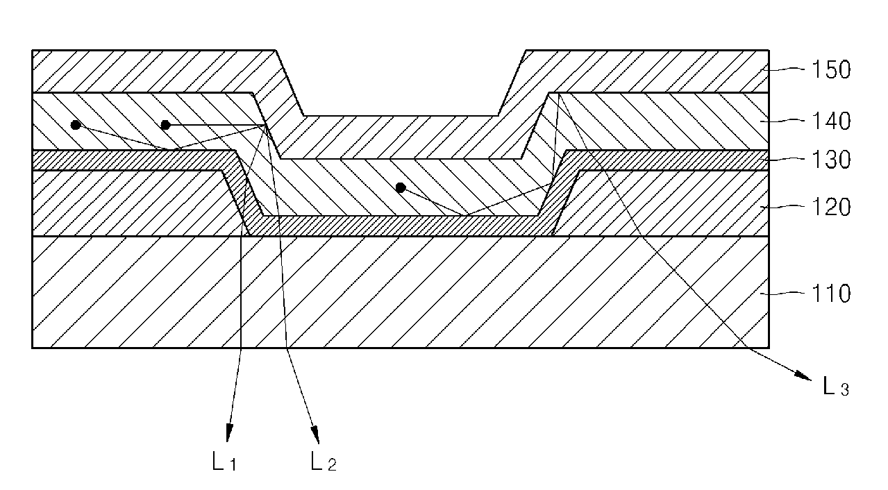
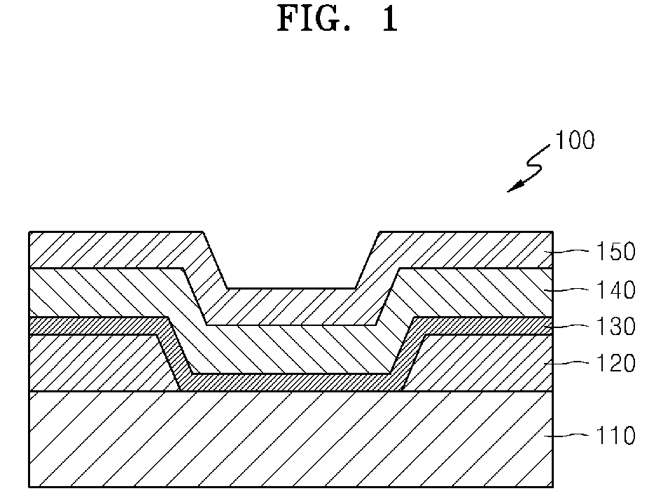
[0046]FIG. 1 is a cross-sectional view of an organic light emitting device 100 according to an embodiment of the present invention. Referring to FIG. 1, the organic light emitting device 100 includes a substrate 110, a first electrode layer 120, a low refractive conductive layer 130, an organic layer 140, and a second electrode layer 150.

[0047]An example of the substrate 110 may include various substrates, such as a glass substrate mainly formed of silicon dioxide (SiO2), and a plastic substrate. The organic light emitting device 100 may be used in a top emission type device in which light is emitted towards the second electrode layer 150, a bottom emi...


PUM


Abstract

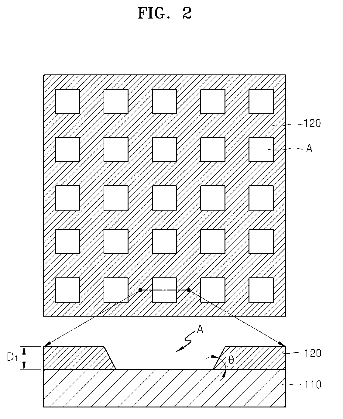
An organic light emitting device having increased outcoupling efficiency, a lighting apparatus including the organic light emitting device, and an organic light emitting display apparatus including the organic light emitting device. The organic light emitting device includes a substrate, a first electrode layer that is uniformly patterned on the substrate, a low refractive conductive layer disposed on the first electrode layer, and having a conductive material with a lower refractive index than a refractive index of an organic layer that is disposed on the low refractive conductive layer, and a second electrode layer formed on the organic layer.

Description

CROSS-REFERENCE TO RELATED APPLICATION[0001]This application claims the benefit of Korean Patent Application No. 10-2009-0114061, filed Nov. 24, 2009 in the Korean Intellectual Property Office, the disclosure of which is incorporated herein by reference.BACKGROUND[0002]1. Field[0003]Aspects of the present invention relate to an organic light emitting device, a lighting apparatus including the organic light emitting device, and an organic light emitting display apparatus including the organic light emitting device, and more particularly, to an organic light emitting device having an increased outcoupling efficiency, a lighting apparatus including the organic light emitting device, and an organic light emitting display apparatus including the organic light emitting device.[0004]2. Description of the Related Art[0005]An organic light emitting device includes an organic emissive layer disposed between electrodes that are opposite to each other. An electron generated by one electrode and...

Claims


Application Information

Patent Timeline
Patent Type & Authority Patents(United States)
IPC IPC(8): H01L51/52
CPCH01L51/5088H01L51/5206H01L51/5262H01L51/5275H01L2251/5361H10K50/17H10K50/813H10K50/85H10K50/858H10K50/828H10K50/856H10K2102/351
Inventor LEE, SUNG-HUNLEE, GWAN-HYOUNGCHU, CHANG-WOONGYOO, SEUNG-HYUPKOH, TAE-WOOKCHOI, JUNG-MIN
Owner SAMSUNG DISPLAY CO LTD
Learn More