
Light guide, light source apparatus and endoscope system

a technology of light guide and endoscope, which is applied in the field of light guide, can solve the problems that the tapered optical fiber alone cannot increase the divergence angle enough to facilitate, and achieve the effect of large divergence angle of exit light from optical fiber, large area, and convenient finding of lesion

Inactive Publication Date: 2013-03-26
FUJIFILM CORP
View PDF20 Cites 9 Cited by
  • Summary
  • Abstract
  • Description
  • Claims
  • Application Information

AI Technical Summary

Benefits of technology

The present invention allows the light to spread out from the optical fiber in a way that makes it easier to find a lesion (an abnormal growth of tissue that can cause damage or disease). This is helpful in diagnostic and therapeutic procedures that require illumination of a large area.

Problems solved by technology

However, the use of the tapered optical fiber alone cannot increase the divergence angle enough to facilitate finding a lesion.

Method used


Image

  • Light guide, light source apparatus and endoscope system
  • Light guide, light source apparatus and endoscope system
  • Light guide, light source apparatus and endoscope system

Examples


Embodiment Construction

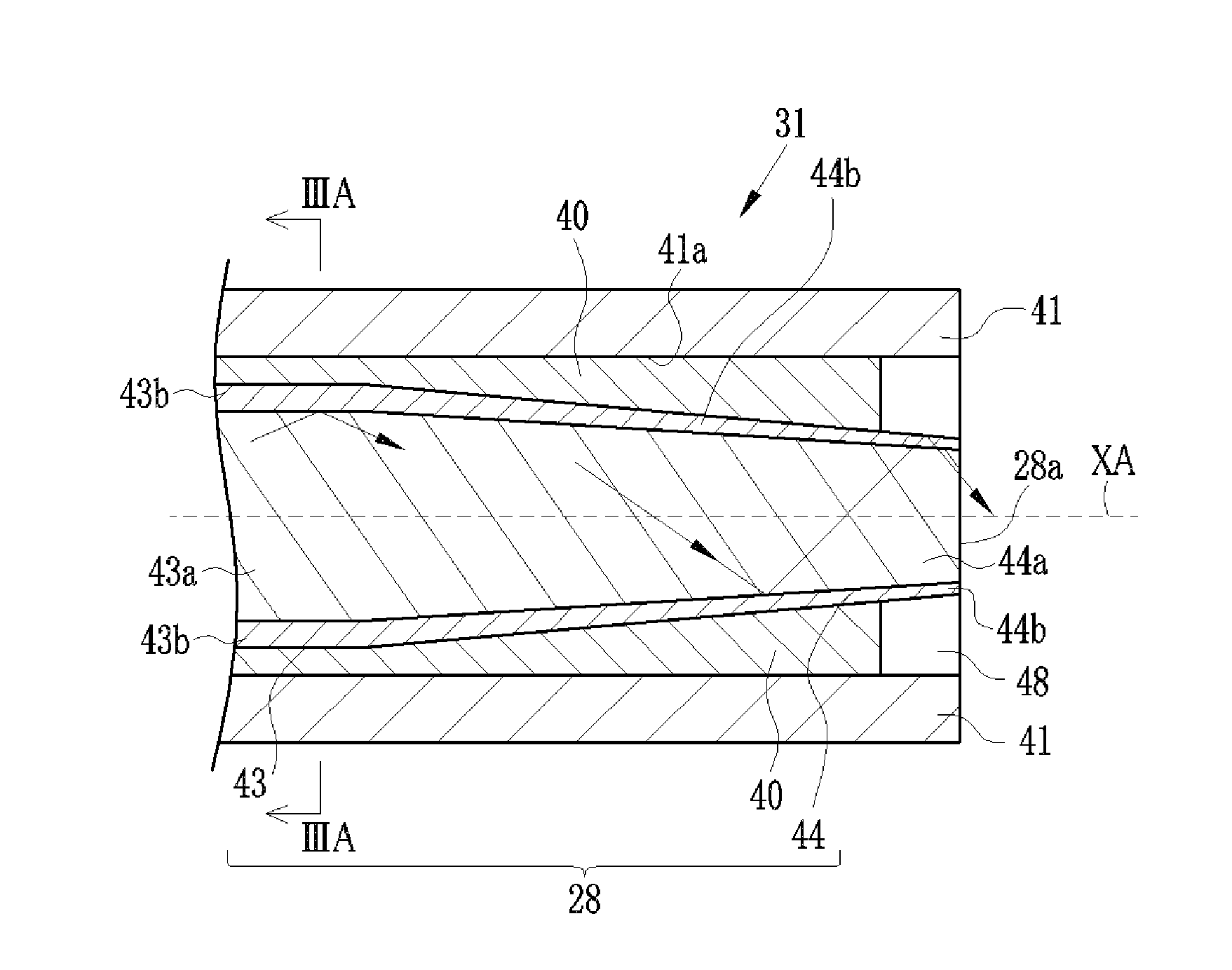
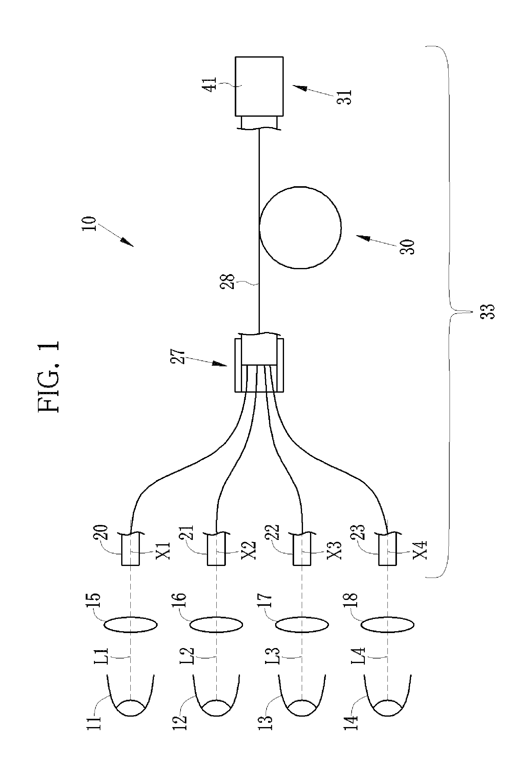
[0023]As shown in FIG. 1, a light source apparatus 10 of the first embodiment of the present invention has light sources 11 to 14, condenser lenses 15 to 18, small diameter optical fibers (hereinafter referred to as small diameter fibers) 20 to 23, a fiber connector 27, a large diameter optical fiber (hereinafter referred to as large diameter fiber) 28, a speckle reducer 30 and a light exit section 31 having an exit surface. In the light exit section 31, the large diameter fiber 28 is retained inside a tubular housing 41.

[0024]The small diameter fibers 20 to 23 are bundled with a ferrule or the like on the light output side. Alight guide 33 is composed of two or more small diameter fibers, in this case, the small diameter fibers 20 to 23, and the large diameter fiber 28. Since the light guide is an optical fiber that transmits light, any one of the small diameter fibers 20 to 23 and the large diameter fiber 28 can be used as the light guide 33.

[0025]The light source 11 and the conde...


PUM


Abstract

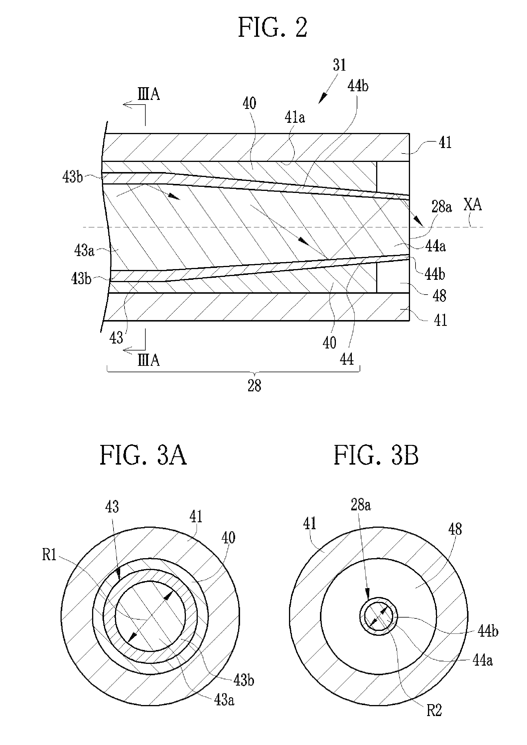
A large diameter fiber is composed of a multimode optical fiber and provided with a fiber body having a constant diameter in an optical axis direction XA and a tapered section tapered in diameter toward a light exit surface. An adhesive member attaches the large diameter fiber inside a retaining hole of a tubular housing such that an outer circumferential surface of a tapered clad of the tapered section is entirely exposed to air to a predetermined depth from the light exit surface. A light passing space is a ring-like space formed between the exposed outer circumferential surface of the tapered clad and an inner circumferential surface of the tubular housing. Light in the tapered section is output from the light exit surface and partially leaked to the tapered clad. A part of the leaked light is released from the light passing space.

Description

FIELD OF THE INVENTION[0001]The present invention relates to a light guide for transmitting light, and also to a light source apparatus and an endoscope system using this light guide.BACKGROUND OF THE INVENTION[0002]A large diameter optical fiber and a bundle fiber having a plurality of optical fibers bundled together are used as laser light guides for transmitting laser beams having specific wavelength(s), such as those for use in laser scalpels (see Japanese Patent Laid-Open Publication No. 2003-086868), and also used as light guides incorporated in endoscopes. The light guide of the endoscope transmits illumination light to illuminate a body cavity of a patient (see Japanese Patent Laid-Open Publication No. 2000-199864 and U.S. Pat. No. 5,888,194 corresponding to Japanese Patent Laid-Open Publication No. 9-166754). In addition, such optical fibers are used for data signal communications (see U.S. Pat. No. 4,877,300, corresponding to Japanese Patent Laid-Open Publication No. 2-163...

Claims


Application Information

Patent Timeline
Patent Type & Authority Patents(United States)
IPC IPC(8): A61B1/06G02B6/36
CPCA61B1/00096A61B1/07G02B6/06A61B1/00071
Inventor SHIMOTSU, SHINICHI
Owner FUJIFILM CORP
Learn More