
Touch panel and interactive input system incorporating the same

a technology of interactive input and touch panel, which is applied in the direction of printed circuit non-printed electric components, electric apparatus casings/cabinets/drawers, instruments, etc., can solve the problems of high manufacturing and shipping costs, high etc., and achieves rapid and easy interconnection, reduce labor and shipping costs, and facilitate assembly

Active Publication Date: 2013-03-19
SMART TECH INC (CA)
View PDF35 Cites 5 Cited by
  • Summary
  • Abstract
  • Description
  • Claims
  • Application Information

AI Technical Summary

Benefits of technology

This solution significantly reduces manufacturing and shipping costs by enabling the touch panel to be assembled on-site, maintaining functionality while obscuring seams for improved aesthetics.

Problems solved by technology

As will be appreciated, manufacturing and shipping such a large scale touch panel is expensive.
Also, as the demand for even larger touch panels increases, so do the associated manufacturing and shipping costs.

Method used


Image

  • Touch panel and interactive input system incorporating the same
  • Touch panel and interactive input system incorporating the same
  • Touch panel and interactive input system incorporating the same

Examples


Embodiment Construction

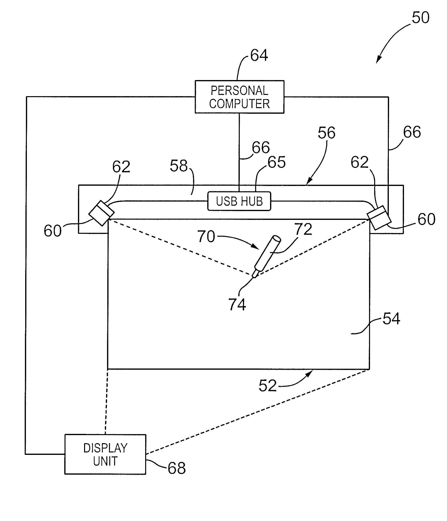
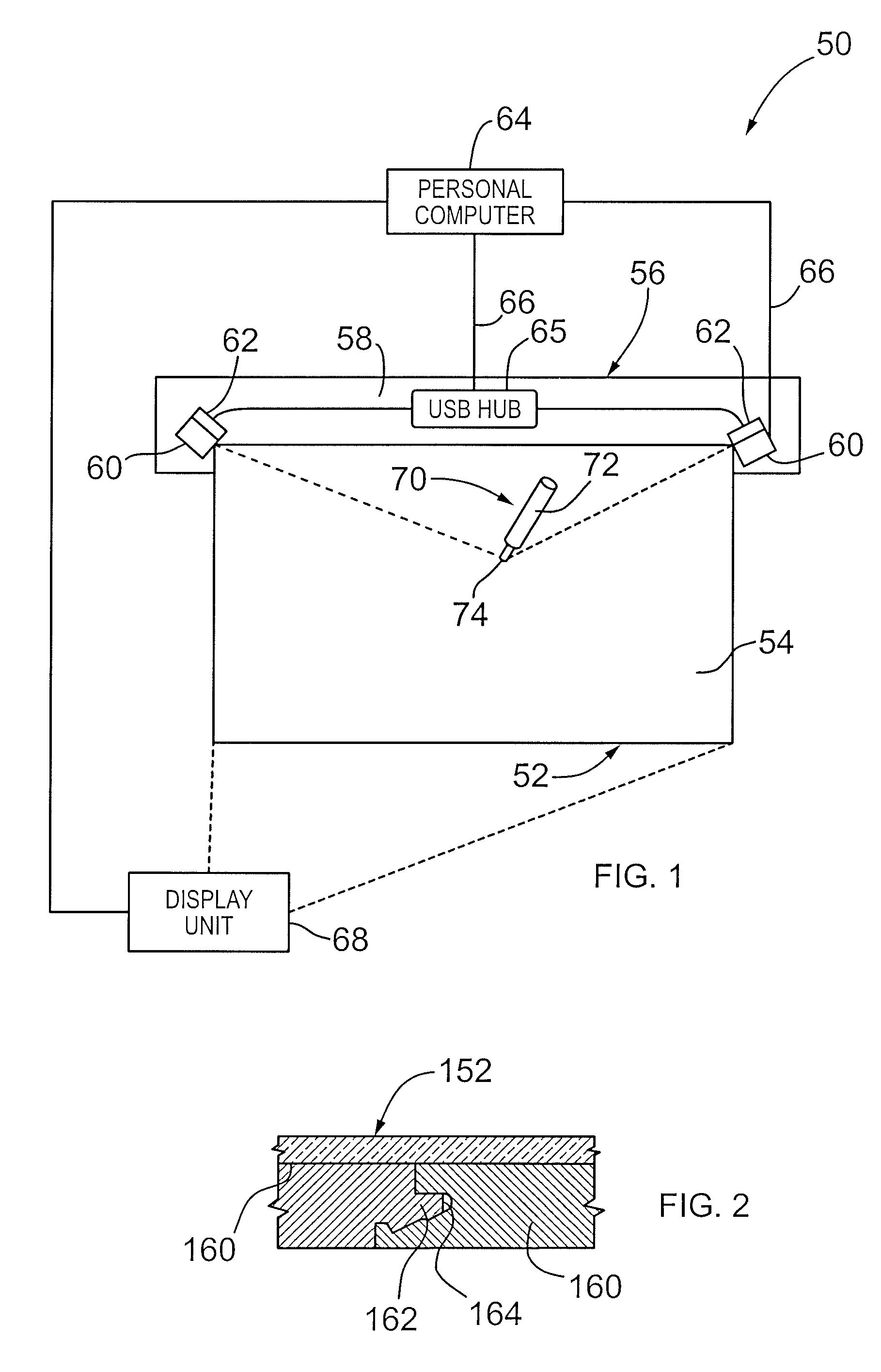
[0024]Turning now to FIGS. 1 and 2, an interactive input system is shown and is generally identified by reference numeral 50. Interactive input system 50 is similar to that described in U.S. patent application Ser. No. 11 / 331,448 to Morrison et al. filed on Jan. 13, 2006, the content of which is incorporated herein by reference. As can be seen, interactive input system 50 comprises an elongate, generally rectangular touch panel 52 defining a touch input surface 54. The input surface 54 may extend over the entire forward face of the touch panel 52 or over a portion thereof. A detection assembly 56 extends along one side of the touch panel 52. The detection assembly 56 includes a valence 58 secured to one side edge of the touch panel 52. Digital cameras 60 are positioned adjacent opposite ends of the valance 58. The fields of view of the digital cameras 60 overlap over the entire input surface 54 so that pointer contacts made on the input surface 54 are visually detected by both digit...


PUM


Abstract

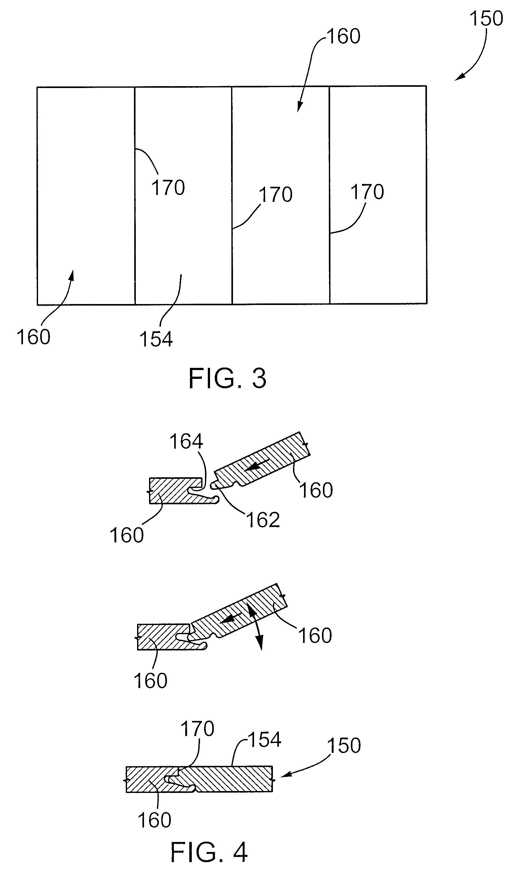
A touch panel comprises a substrate having a forward major surface and formed of a plurality of assembled substrate segments. Cover material overlies the forward major surface to reduce the visibility of seams between adjacent substrate segments.

Description

FIELD OF THE INVENTION[0001]The present invention relates generally to interactive input systems and in particular to a touch panel and to an interactive touch system incorporating the same.BACKGROUND OF THE INVENTION[0002]Touch systems are well known in the art and typically include a touch screen or panel having a touch or input surface on which contacts are made using a pointer in order to generate user input. Pointer contacts with the touch surface are detected and are used to generate corresponding output depending on areas of the touch surface where the contacts are made. Many types of touch systems exist that utilize different technologies to identify pointer contacts with the touch surface. These technologies include for example analog resistive, electromagnetic, capacitive, acoustic or machine-vision detection arrangements to identify pointer contacts with the touch surface.[0003]For example, International PCT Application No. PCT / CA01 / 00980 filed on Jul. 5, 2001 and publish...

Claims


Application Information

Patent Timeline
Patent Type & Authority Patents(United States)
IPC IPC(8): G09G5/00G06F3/039
CPCG06F3/039G03B21/58G06F3/0428G06F3/0393G06F3/0412G06K11/06
Inventor OLESKEVICH, TANYAROBERTSON, DONMARTIN, NICOLE
Owner SMART TECH INC (CA)
Learn More