Film formation method and film formation apparatus
a film formation method and film technology, applied in the direction of liquid surface applicators, coatings, chemical vapor deposition coatings, etc., can solve the problems of insufficient study of how to adjust the film quality, the difficulty of keeping the film quality constant, and the inability to keep the film thickness constant, so as to achieve high and stable concentration of microparticles in the aerosol, the effect of low variance in the film quality
- Summary
- Abstract
- Description
- Claims
- Application Information
AI Technical Summary
Benefits of technology
Problems solved by technology
Method used
Image
Examples
embodiment 1
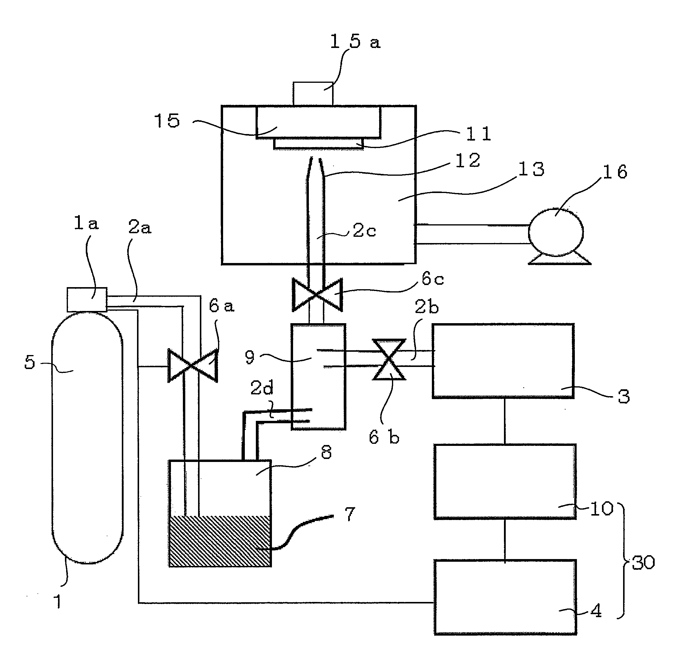
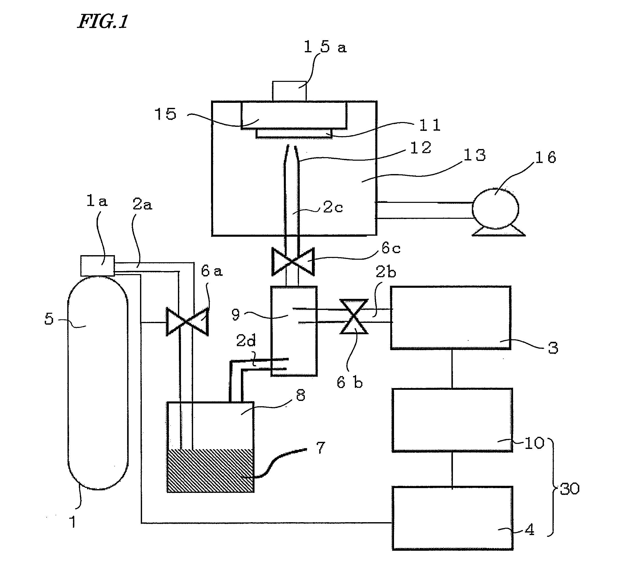
[0046]FIG. 1 schematically shows a film formation apparatus in an embodiment according to the present invention. As shown in FIG. 1, the film formation apparatus in this embodiment includes a first chamber 8, a second chamber 9 connected to the first chamber 8, a third chamber 13 connected to the second chamber 9, a particle measurement section 3 connected to the second chamber 9, and a control mechanism 30 connected to the particle measurement section 3.
[0047]The first chamber 8 is connected to a gas cylinder 1 via a pipe 2a. The gas cylinder 1 is filled with helium used as a carrier gas 5. At a portion at which the gas cylinder 1 is connected to the pipe 2a, a pressure adjustment section 1a for adjusting a pressure of the carrier gas 5 is provided. The pipe 2a is provided with a control valve 6a for controlling the supply of the carrier gas 5 from the gas cylinder 1.
[0048]The first chamber 8 accommodates material powders 7, and a tip of the pipe 2a is inserted into the material po...
embodiment 2
[0076]FIG. 4 schematically shows a film formation apparatus in an embodiment according to the present invention. In FIG. 4, identical elements as those in FIG. 1 bear identical reference numerals therewith. Unlike the film formation apparatus shown in FIG. 1, the film formation apparatus shown in FIG. 4 includes none of the particle measurement section 3, the control mechanism 30, the pipe 2b, and the nozzles 6b and 6c.
[0077]Hereinafter, a film formation method in this embodiment will be described with reference to FIG. 4.
[0078]According to the film formation method in this embodiment, first, the control valve 6a is opened and closed repeatedly at the cycle of a constant period to introduce the carrier gas 5 from the gas cylinder 1 to the first chamber 8 intermittently. When the carrier gas 5 is introduced to the first chamber 8, the material particles 7 accommodated in the first chamber 8 and the carrier gas 5 are mixed together to generate first aerosol. The first aerosol is intr...
example 1
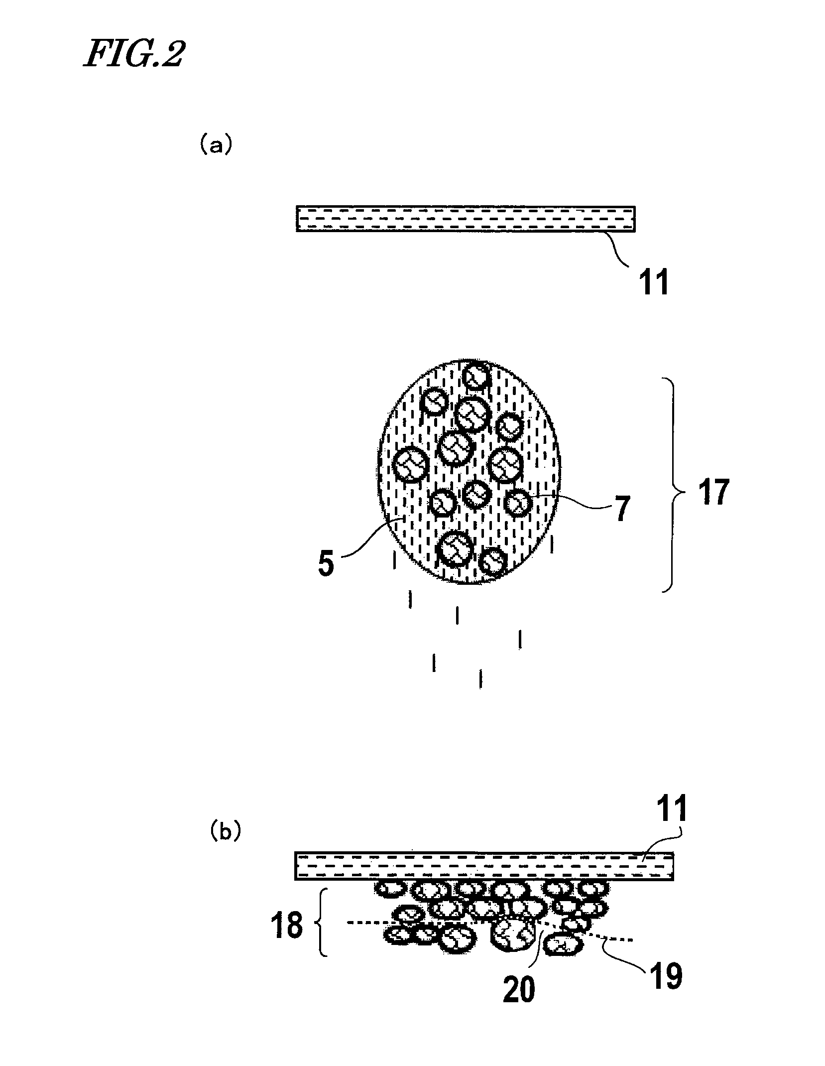
[0106]An AD film was actually produced, and the AD film was used to measure the relationship of the particle diameter and the concentration of the aerosol with respect to the film formation rate and the density of the AD film. Hereinafter, the results will be described.
[0107]First, a specific structure of a film formation apparatus used for forming the AD film will be described with reference to FIG. 1 again. As shown in FIG. 1, in the third chamber 13 which is a film formation chamber, the substrate 11 formed of Al and having a thickness of 15 μm is fixed to the substrate holder 15. The inside of the third chamber 13 is kept in a vacuum state by the exhaust pump 16. The nozzle 12 for supplying the aerosol is located to face the surface of the substrate 11. The nozzle 12 has a circular jetting opening having a diameter of 1 mm. The pipe 2c connected to the nozzle 12 is drawn to the outside of the film formation chamber 13 and connected to the second chamber 9. In the middle of the p...
PUM
| Property | Measurement | Unit |
|---|---|---|
| width | aaaaa | aaaaa |
| length | aaaaa | aaaaa |
| diameter | aaaaa | aaaaa |
Abstract
Description
Claims
Application Information
 - R&D
- Intellectual Property
- Life Sciences
- Materials
- Tech Scout
- Unparalleled Data Quality
- Higher Quality Content
- 60% Fewer Hallucinations
Browse by: Latest US Patents, China's latest patents, Technical Efficacy Thesaurus, Application Domain, Technology Topic, Popular Technical Reports.
© 2025 PatSnap. All rights reserved.Legal|Privacy policy|Modern Slavery Act Transparency Statement|Sitemap|About US| Contact US: help@patsnap.com


