
Method and device for reconstructing a three-dimensional scene with corrected visibility

a three-dimensional scene and visibility technology, applied in the field of three-dimensional scene reconstruction, can solve the problems of insufficient compliance with requirements and possible reconstruction errors, and achieve the effect of saving computing power and simplifying the method

Active Publication Date: 2013-02-26
SEEREAL TECHNOLOGIES
View PDF4 Cites 8 Cited by
  • Summary
  • Abstract
  • Description
  • Claims
  • Application Information

AI Technical Summary

Benefits of technology

The patent text describes a way to analyze the visibility of an image using a small window. The method involves adjusting the visibility function based on the size of the image and the size of the window. This simplifies the analysis and saves computing power. The technical effect of this method is to make it easier to analyze visibility in images.

Problems solved by technology

However, if the visibility region is larger than the eye pupil, this does not fully comply with the requirements specified above with a view to a realistic representation of the 3D scene.
Although the change of the perspective as such, i.e. the relative displacement of object points within planes which are situated at different distances to the observer, is already considered in a thus computed hologram, errors in the reconstruction may occur in this case if the observer moves outside the centre of the visibility region.
These errors are due to the fact that natural variations in brightness, at which individual parts of a 3D scene are visible from different perspectives, are not considered in the reconstruction.

Method used


Image

  • Method and device for reconstructing a three-dimensional scene with corrected visibility
  • Method and device for reconstructing a three-dimensional scene with corrected visibility
  • Method and device for reconstructing a three-dimensional scene with corrected visibility

Examples


Embodiment Construction

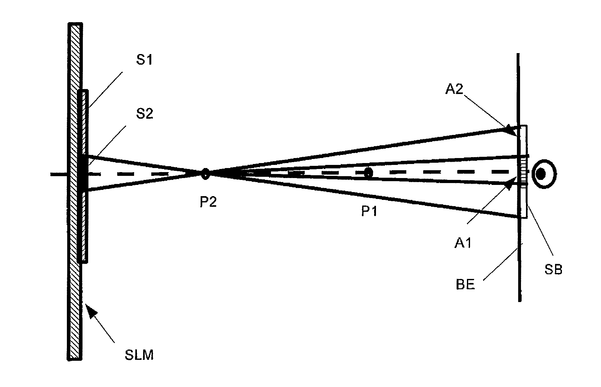
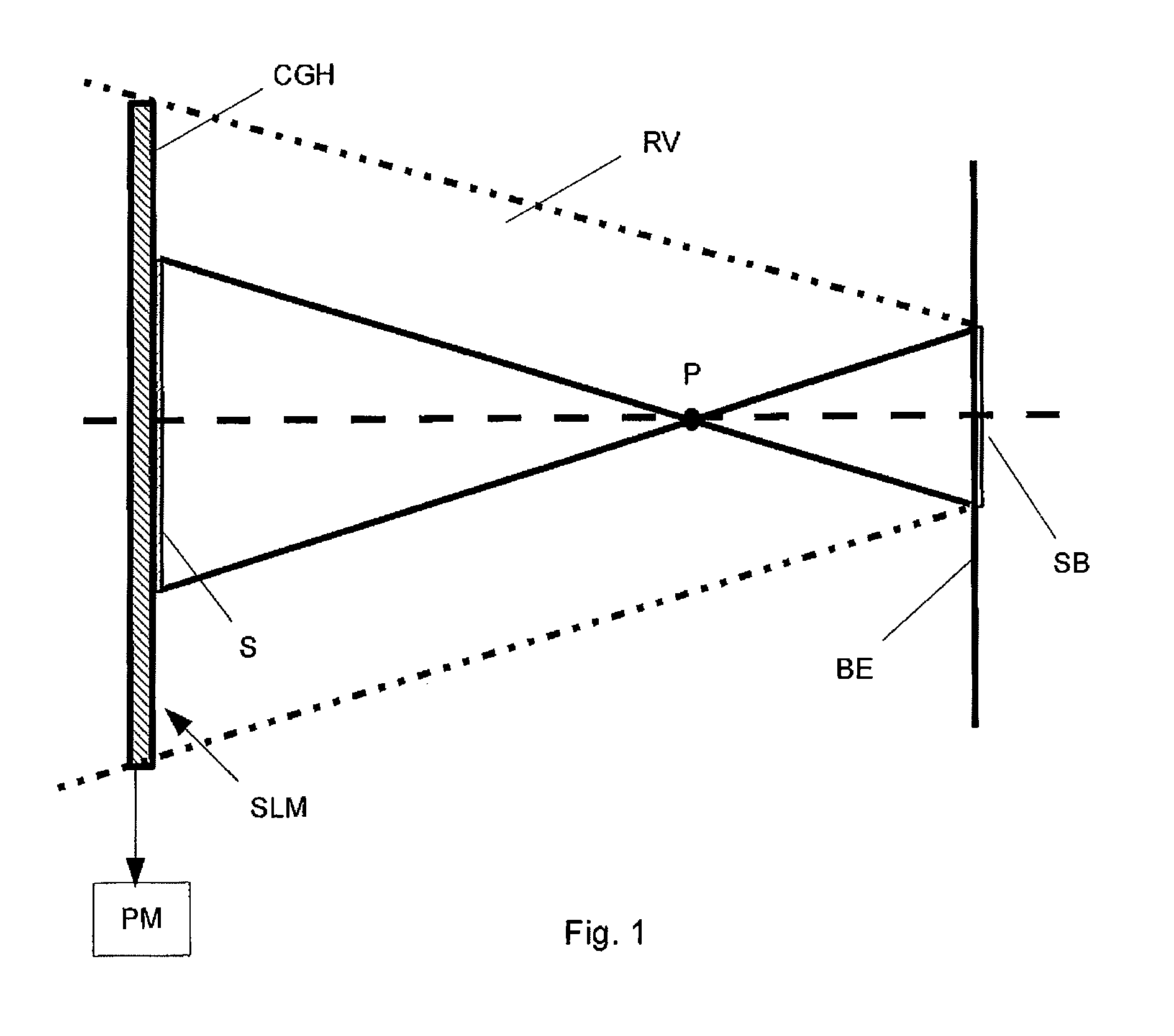
[0052]It is known from the prior art to separate the 3D scene into section layers which are parallel to the plane of an SLM and to transform all of those section layers into a visibility region SB in the observer plane BE and to add their values there. Then, the 3D scene is computed in the hologram plane by way of another transformation of those aggregated values into the light modulator, and encoded as a CGH on the SLM.

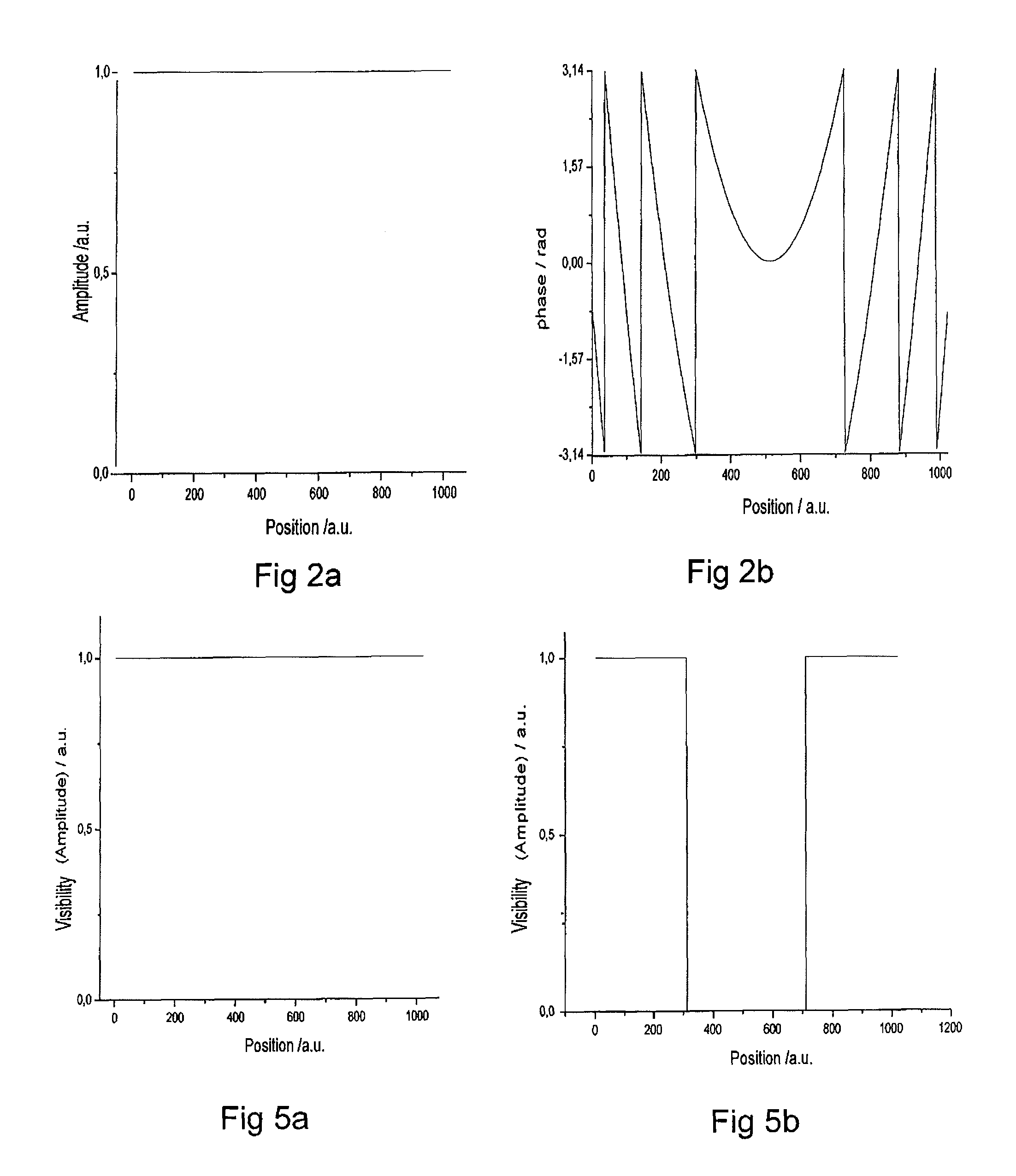
[0053]In contrast, according to the inventive method, the 3D scene is separated into individual object points P; . . . ; Pn, and each individual object point Pn is discretely transformed into the visibility region SB. The transformation of an individual object point Pn initially generates in the visibility region SB a constant intensity and a phase gradient which depends on the position of the object point Pn in the respective section layer, or in the 3D scene. The entire distribution of values in the visibility region SB is found by way of adding the complex values ...


PUM


Abstract

A method is disclosed for reconstructing a 3D scene made of object points in a holographic display, wherein the reconstruction is visible from a visibility region. Visibility and / or covering of parts of the 3D scene corresponding to the real parameters is realized, with the reconstruction, for a viewer from every place of the visibility region. Processor means generate a spatial point matrix for defining the positions of individual object points, which are assigned predetermined intensity and phase values. Within the visibility region, a complex-value wave front for each single object point is calculated. The intensity values of the object points are multiplied with the associated visibility function, to determine a common modified wave front of the object points, transformed into the plane of a light modulator to calculate modified control values for the object points.

Description

CROSS REFERENCE TO RELATED APPLICATIONS[0001]This application claims the priority of PCT / EP2008 / 052903, filed on Mar. 12, 2008, which claims priority to German Application No. 10 2007 013 431.4, filed Mar. 15, 2007, the entire contents of which are hereby incorporated in total by reference.BACKGROUND OF THE INVENTION[0002]The present invention relates to a method for presenting an observer a holographically reconstructed three-dimensional scene (3D scene), and to a holographic display device in which this method is implemented.[0003]The field of application of the invention includes holographic display devices in sectors where a very detailed and realistic representation of 3D scenes is essential. This can for example be the medical, geological or military industry, in order to plan operations, drill-holes and other activities precisely and thus to reduce costs considerably and / or to minimise risks. In addition, such display devices may be used in the private sector, e.g. for games....

Claims


Application Information

Patent Timeline
IPC IPC(8): G03H1/08G03H1/26G02B5/32G03H1/22
CPCG03H1/0808G03H1/22G03H1/2294G03H2001/0825G03H2210/30G03H2210/452G03H2210/454G03H2210/441G03H2210/36
Inventor LEISTER, NORBERT
Owner SEEREAL TECHNOLOGIES
Learn More