
Printing apparatus and control method with adjustment unit correcting the displacement of the print position by pixel unit, and another unit correcting the displacement by the unit smaller than the pixel

a printing apparatus and control method technology, applied in the field of printing apparatus, can solve the problems of serial type inkjet printing apparatus having an inherent problem, large apparatus, and many other problems, and achieve the effects of reducing printing speed, high accuracy, and increasing cos

Inactive Publication Date: 2013-02-26
CANON KK
View PDF26 Cites 8 Cited by
  • Summary
  • Abstract
  • Description
  • Claims
  • Application Information

AI Technical Summary

Benefits of technology

The present invention aims to provide an inkjet printing apparatus that can correct the tilting of the printing head with high accuracy without reducing printing speed or increasing cost. This patent text proposes a control method for the inkjet printing apparatus.

Problems solved by technology

Although the line type printing apparatus can perform printing rapidly, such an apparatus tends to be large.
However, the serial type inkjet printing apparatus also has an inherent problem.
During the manufacture of a printing head and a printing apparatus, specific errors must be taken into account, but various other discrepancies are also often found in the print results.
A plurality of printing elements are arranged in a printing head under the same conditions; however, specific discrepancies may be present in the consumption of the driving power by the individual printing elements, and in members provided in the printing elements.
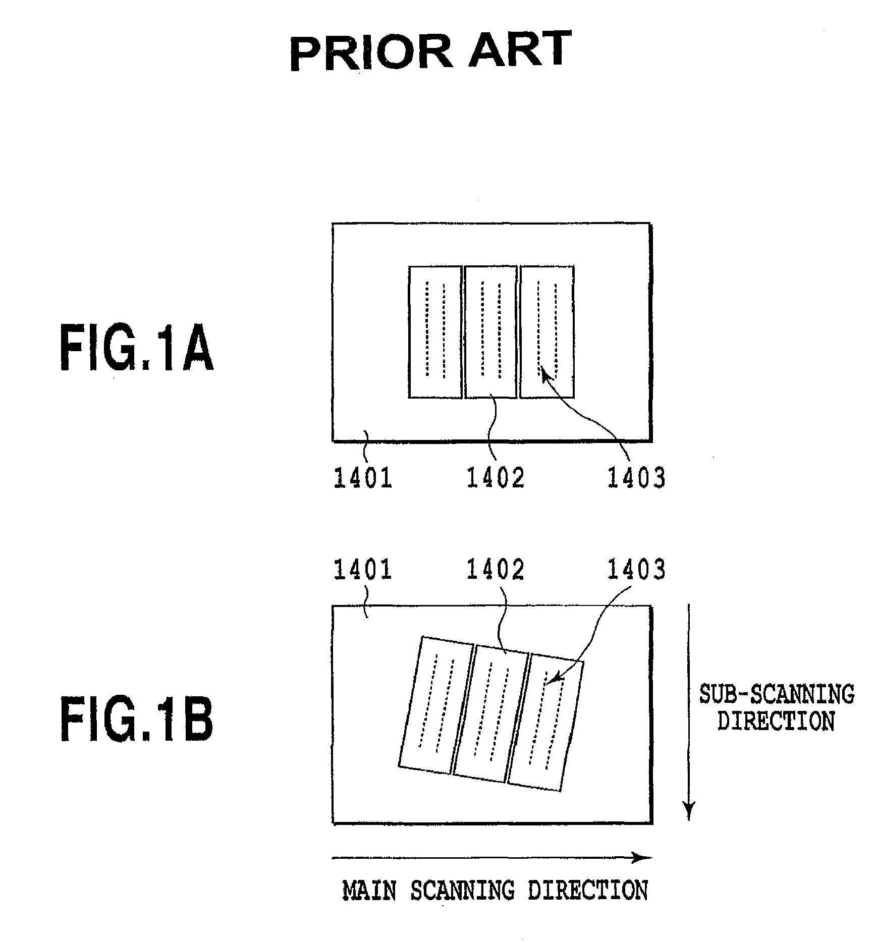
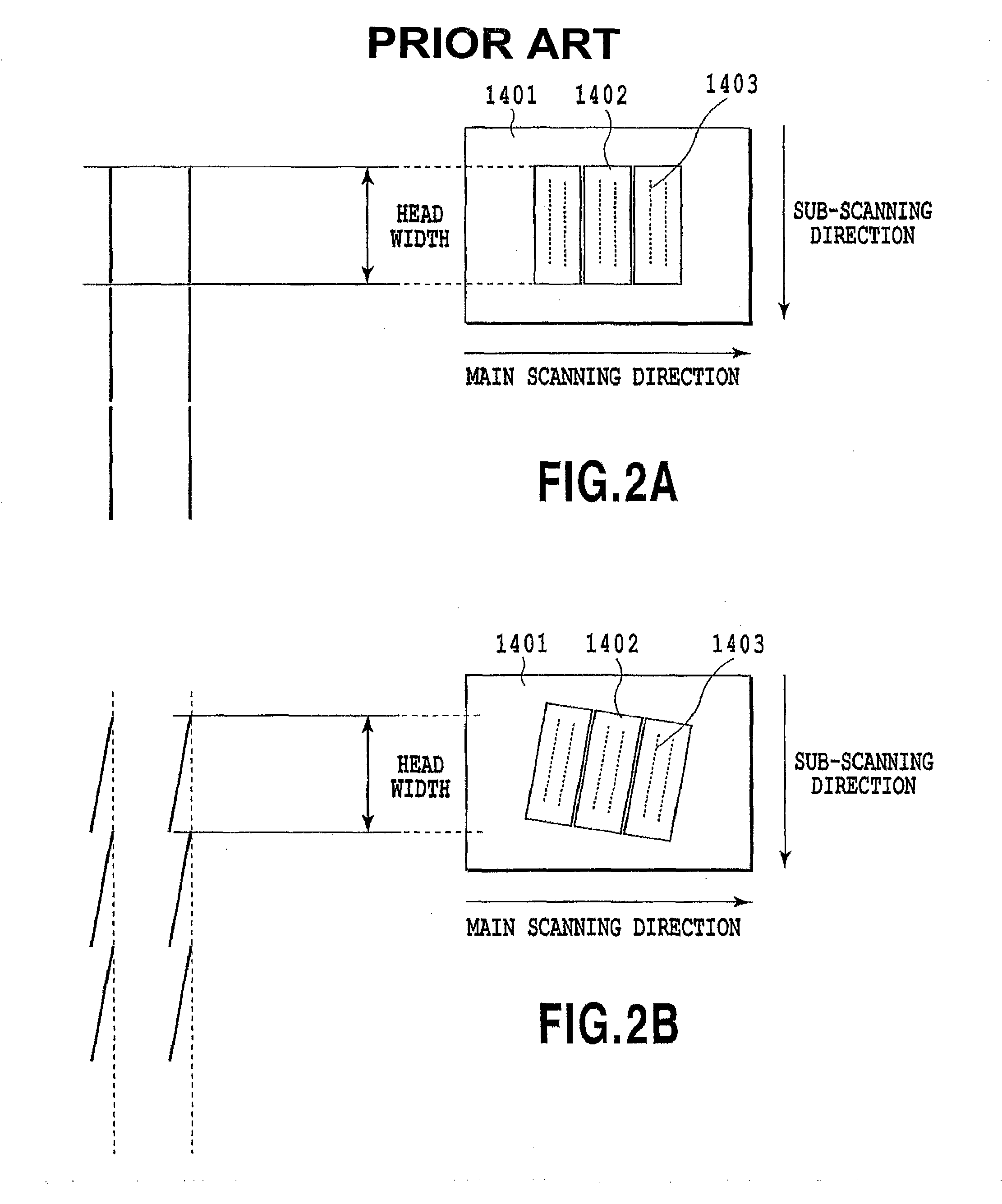
Further, such differences in the print positions constitute a new image barrier for various situations, in addition to the printing of the ruled lines shown in FIG. 2B.
However, when the above described tilt is present, even though the multi-pass printing method is employed, a displacement may occur in dot position to be complemented each scan, and a new image barrier, such as improper texture, may be the result.
Because of this, color would be applied unevenly, or granularity deterioration (visual roughness of grains) would occur.
As described above, an image barrier due to tilting is a conventionally important problem for a serial inkjet printing apparatus.
However, by using the methods described in the patent documents described above, wither the above described problems can not be satisfactorily resolved or a new another problem has arisen, and practical tilting correction is not ensured.
However, according to the first method, since drive signal transmission means for the individual nozzle groups is required, costs are increased, and the limit “the maximum value for a shift is dependent on the input of a data signal for an adjacent pixel” is also additionally provided.
According to the second method, no limitations are imposed for the shift, however, when an accurate correction is to be performed, a higher resolution must be set for data to be printed, and the amount of image data required would be enormous.
However, according to this method, as well as the method disclosed in Japanese Patent Laid-Open Publication No. 7-309007, the limitation that “the maximum value for a shift is dependant on the input of a data signal for an adjacent pixel” is additionally provided.
Therefore, the correctable range is limited to only a single pixel.
However, using either of the methods disclosed in Japanese Patent Application Laid-open Nos. 11-240143 (1999) and 2004-009489, corrections can only be performed at accuracy equal to a unit of a single pixel.
Thus, this is not a practical method.

Method used


Image

  • Printing apparatus and control method with adjustment unit correcting the displacement of the print position by pixel unit, and another unit correcting the displacement by the unit smaller than the pixel
  • Printing apparatus and control method with adjustment unit correcting the displacement of the print position by pixel unit, and another unit correcting the displacement by the unit smaller than the pixel
  • Printing apparatus and control method with adjustment unit correcting the displacement of the print position by pixel unit, and another unit correcting the displacement by the unit smaller than the pixel

Examples


first embodiment

[0060]An explanation will now be given for specific embodiments of the present invention where the above described inkjet printing apparatus is employed.

[0061]FIG. 9 is a diagram for explaining the state of an inkjet printing head for a first embodiment of the invention wherein discharge ports of printing elements are arranged. For the printing head of this embodiment, two discharge port arrays L1 and L2 are arranged to discharge one color ink, and in FIG. 9, black squares indicate discharge ports included in the individual arrays. To form one discharge port array, 64 discharge ports are arranged at a pitch Py of 1 / 300 inches in the sub-scanning direction, and two discharge port arrays are shifted by a distance Py / 2 from each other in the sub-scanning direction. When this printing head is moved in the main scanning direction and discharges ink at a predetermined timing, an image can be printed at a printing density of 600 dpi in the sub-scanning direction. For the convenience sake o...

second embodiment

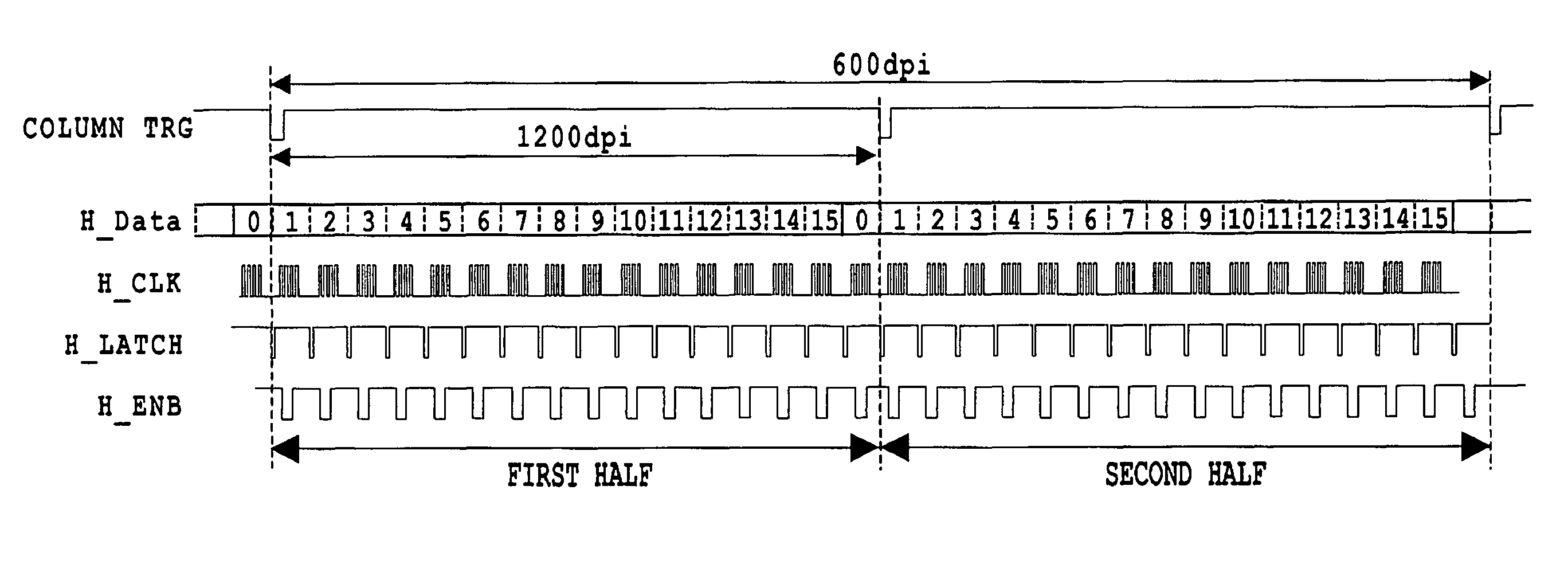
[0080]A second embodiment of the present invention will now be described. A printing apparatus in this embodiment prints an image at a resolution of 300 dpi, and a first print position adjustment means performs correction for each pixel of 300 dpi. The arrangement in FIG. 9 is also employed for the discharge port array of a printing head and Seg_Blocks in this embodiment; however, the pitch for arranging discharge ports is equivalent to 300 dpi. In this embodiment, the conventional structure that provides different H_ENB signals for individual Seg_Blocks is employed for a second print position adjustment means.

[0081]FIG. 13 is a diagram showing the connections of E_ENB signals to Seg_Blocks in a printing head for the embodiment. As shown in FIG. 13, independent H_ENB signals are provided for individual Seg_Blocks, and can be separately controlled. The H_ENB signals may be independently generated by the main body of the printing apparatus. Or, the connector of the printing head or a ...


PUM


Abstract

Provided is a print position control method whereby displacement of a print position in a wide range can be corrected very accurately, without reducing a printing speed or increasing a manufacturing cost. Thus, a printing apparatus includes: a first correction unit, for correcting a print position at accuracy equal to the resolution of the printing apparatus; and a second correction unit, for correcting the print position at accuracy higher than the resolution and in the range of an area that corresponds to one pixel of the resolution. With this arrangement, the print position displacement in a wide range equal to or greater than one pixel can be corrected by the first correction unit, and a print position displacement smaller than one pixel can be corrected by the second correction unit. Therefore, correction of a print position displacement in a wide range is enabled at a higher accuracy.

Description

BACKGROUND OF THE INVENTION[0001]1. Field of the Invention[0002]The present invention relates to a printing apparatus wherein a printing unit, in which a plurality of printing elements are arranged, provides a printing agent for a printing medium to form an image. The present invention relates particularly to a method and a configuration for adjusting the displacement of print position for printing elements.[0003]2. Description of the Related Art[0004]Printing apparatuses having some function of a printer, a copiers and a facsimile, or printing apparatuses employed as the output apparatuses for multifunctional electronic apparatuses that include a computer or a word processor and for workstations employ image information (including, for example, character information) to print images (including characters and like) on printing media, such as paper and plastic thin sheets. The printing methods of the printing apparatuses can be categorized as being inkjet, wire dot, thermal and laser...

Claims


Application Information

Patent Timeline
Patent Type & Authority Patents(United States)
IPC IPC(8): G06K15/00
CPCB41J2/2135B41J29/393
Inventor KAWATOKO, NORIHIROHAMASAKI, YUJISAKAMOTO, ATSUSHIHAYASHI, AYAKANDA, HIDEHIKOCHIKUMA, TOSHIYUKIMORIYAMA, JIRO
Owner CANON KK
Learn More