
Organic light-emitting diodes

a light-emitting diode and organic technology, applied in the field of multi-layered organic light-emitting diodes, can solve the problems of reducing the life span of the element, obtaining a sufficient coating performance, and materials that are not easy to handle during processing, so as to improve the light-emitting efficiency of the light-emitting diode, and improve the light-emitting efficiency

Active Publication Date: 2013-02-26
KOREA ADVANCED INST OF SCI & TECH
View PDF2 Cites 11 Cited by
  • Summary
  • Abstract
  • Description
  • Claims
  • Application Information

AI Technical Summary

Benefits of technology

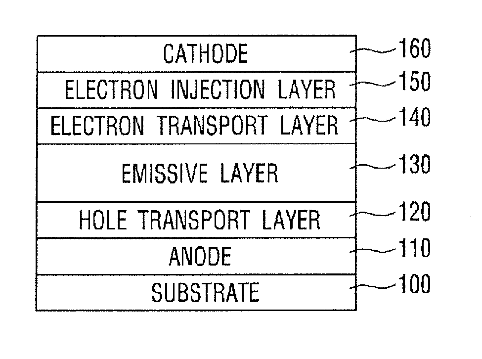
[0013]Therefore, according to the organic light-emitting diodes related to claim 1, the organic light-emitting diodes including a ZnO nanoparticle and an ionic group is easily formed by using a solution process. Therefore, a high temperature heat treatment process is not performed, thereby having no influence on a light-emitting organic material vulnerable to heat. It is possible to increase the light emission efficiency of the organic light-emitting diodes and to protect the organic material from the external moisture and oxygen by using excellent electron injection properties and excellent electron transport properties of ion and ZnO nanoparticle within the electron injection layer. Since a solution process can be applied to layers as all as possible, the organic light-emitting diodes can be easily and inexpensively manufactured. In the organic light-emitting diodes related to claim 1, since a substrate made of a flexible plastic material, that is, a flexible substrate is used, it is possible to manufacture a flexible light-emitting diodes which can be curved and adhered to variously curved surfaces.
[0041]Therefore, according to the organic light-emitting diodes related to claim 16, the organic light-emitting diodes which is formed by inverting the layers of the organic light-emitting diodes related to claim 15 and by merging the electron injection layer and the electron transport layer into one layer and which includes a ZnO nanoparticle and an ionic group is easily formed by using a solution process. Therefore, a high temperature heat treatment process is not performed, thereby having no influence on a light-emitting polymer flexible substrate vulnerable to heat. It is possible to increase the light emission efficiency of the light-emitting diodes by using excellent electron transport properties of ion and ZnO nanoparticle within the electron injection transport layer, and possible to inexpensively manufacture the organic light-emitting diodes.

Problems solved by technology

When a cathode is additionally deposited, the above layer is very vulnerable to oxygen and moisture in the outside air, so that the life span of the element is reduced.
Moreover, these materials are not easy to handle during processing.
Therefore, since it is not easy to obtain a sufficient coating performance through the solution process such as a roll-to-roll coating, an inkjet printing, a screen printing, a spray coating and a dip coating, it is very difficult to apply the ultrathin electron injection layer to the solution process.
When a metal having a high work function is used as a cathode, there is a problem that the performance of the organic light-emitting diodes is greatly reduced.
When an alkali metal or alkaline earth metal which has a low work function is used as a cathode, such a cathode is vulnerable to oxygen and moisture in the air.
Accordingly, it has been difficult to handle the cathode and a high-degree vacuum had to be maintained during the process.
Therefore, when the polar solvent is coated on an organic emissive layer, a polar polymer material having an ion group is agglomerated, and when the polar solvent is coated on a hydrophobic emissive layer, a aggregated coating degradation like stain occurs, so that the hydrophilic polymer material or an electrolytic ion complex, which has an ion group, is difficult to be applied to mass production due to their coating problems.
Accordingly, in most cases, it is required that a material having an ion group be doped in or added to the emissive layer, and ions freely float within the emissive layer, which has a bad influence on the emission performance of the device.

Method used


Image

  • Organic light-emitting diodes
  • Organic light-emitting diodes
  • Organic light-emitting diodes

Examples


embodiment 1

[0064]Further, the electron injection layer 150 may be formed by using a metal ion. The metal ion forms the ZnO nanoparticle of the electron transport layer and compounds such as ZnO:Cs, ZnO:Li, ZnO:Mg, ZnO:Al, ZnO:Ca, ZnO:Na and ZnO:Ba. According to the method for forming the electron injection layer 150 by using the metal ion, LiF, CsF, NaF, Cs2CO3, Ca(acac)2 and the like of the salt of the liquefiable alkali metal and liquefiable alkaline earth metal are dissolved in a polar solvent, and then this solution is used to form the electron injection layer 150. According to a method using a depositing metallic material as the electron injection layer, the alkali metal and alkaline earth metal such as Ca, Na, Mg, Li, Ba and Cs and the like and LiF, CsF, NaF, Cs2CO3, Ca(acac)2 of a salt form are deposited. An example that the electron injection layer 150 of the first organic light-emitting diodes is formed by using the metal ion as mentioned above will be described in the following

[0065]...

embodiment 2

[0072]With respect to the electron injection layer 150, the electron injection effect can be increased not only by adding an organic polymer material and organic low molecular weight material which include ammonium salts or an organic polymer material and organic low molecular weight material which include amino group, but also by using the surfactant and organic salts of ammonium series. This corresponds to the following description of

[0073]The electron injection layer 150 is formed by using an ionic polymer material including an ionic group, and is also formed by using an n-type polymer material or an n-type low molecular weight material. An example that the electron injection layer 150 of the first organic light-emitting diodes is formed by using the ionic polymer material including an ionic group will be described in the following embodiment 2.

[0074][Embodiment 2]

[0075]Anode: manufactured with indium tin oxide (ITO) glass, deionized water, acetone and isopropyl alcohol (IPA) are...

embodiment 4

[0090]An example of forming the electron injection layer 220 of the second organic light-emitting diodes by using metal ion will be described in the following


PUM


Abstract

Disclosed is an organic light-emitting diodes including a ZnO nanoparticle and an ionic group. The organic light-emitting diodes according to the present invention includes:a substrate formed of glass or a flexible plastic material;an anode formed on the substrate;a hole transport layer formed on the anode;an emissive layer formed on the hole transport layer;an electron transport layer being formed on the emissive layer and including a ZnO nanoparticle;an electron injection layer being formed on the electron transport layer and including an ionic group; anda cathode formed on the electron injection layer.

Description

CROSS-REFERENCE TO RELATED APPLICATIONS[0001]This U.S. National stage application claims priority under 35 U.S.C. §119(a) to Korean Patent Application No. 10-2010-0048136, filed in the Republic of Korea on May 24, 2010, the entire contents of which are hereby incorporated herein by reference.BACKGROUND OF THE INVENTION[0002]1. Field of the Invention[0003]The present invention relates to a multi-layered organic light-emitting diodes.[0004]2. Description of the Related Art[0005]Recently, with a solution process applicable to not only a polymer organic light-emitting diodes but also a low molecular weight organic light-emitting diodes, many attempts are being made to apply a printing method to the solution process. The solution process includes an inkjet printing, a roll-to-roll printing, a screen printing, a spray coating and a dip coating and the like.[0006]However, an anode and a cathode are still manufactured in vacuum by sputtering or evaporation. Since the aforesaid process requi...

Claims


Application Information

Patent Timeline
Patent Type & Authority Patents(United States)
IPC IPC(8): H01L51/52
CPCH01L51/5048H01L51/5092H01L2251/5369H10K50/14H10K50/171H10K2102/331
Inventor YANG, MINYANGYOUN, HONGSEOK
Owner KOREA ADVANCED INST OF SCI & TECH
Learn More