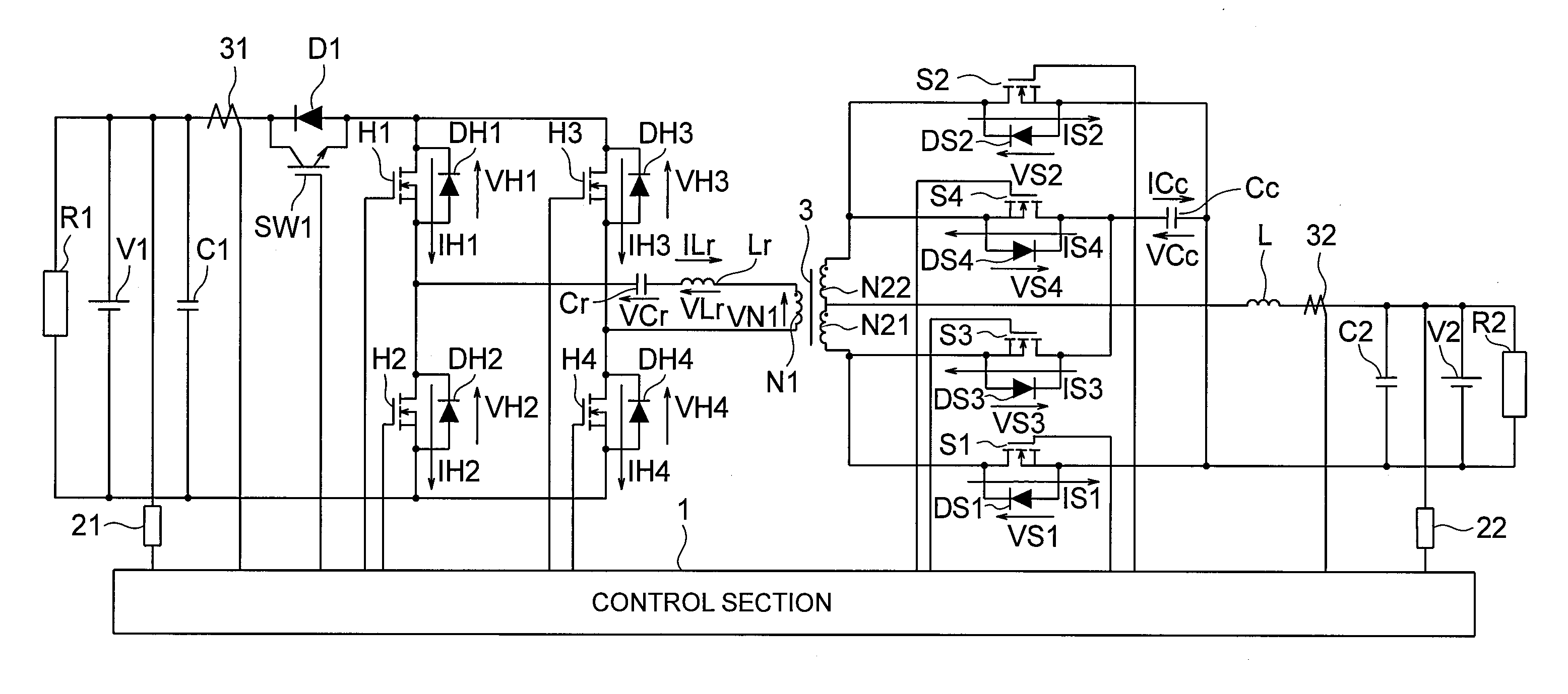
Bidirectional dc-dc converter and control method thereof
a dc-dc converter and bi-directional technology, applied in process and machine control, emergency power supply arrangements, instruments, etc., can solve problems such as obstructed downsizing and efficiency improvement, and achieve low switching loss, fast switching characteristics, and slow body diode reverse recovery characteristics
- Summary
- Abstract
- Description
- Claims
- Application Information
AI Technical Summary
Benefits of technology
Problems solved by technology
Method used
Image
Examples
first embodiment
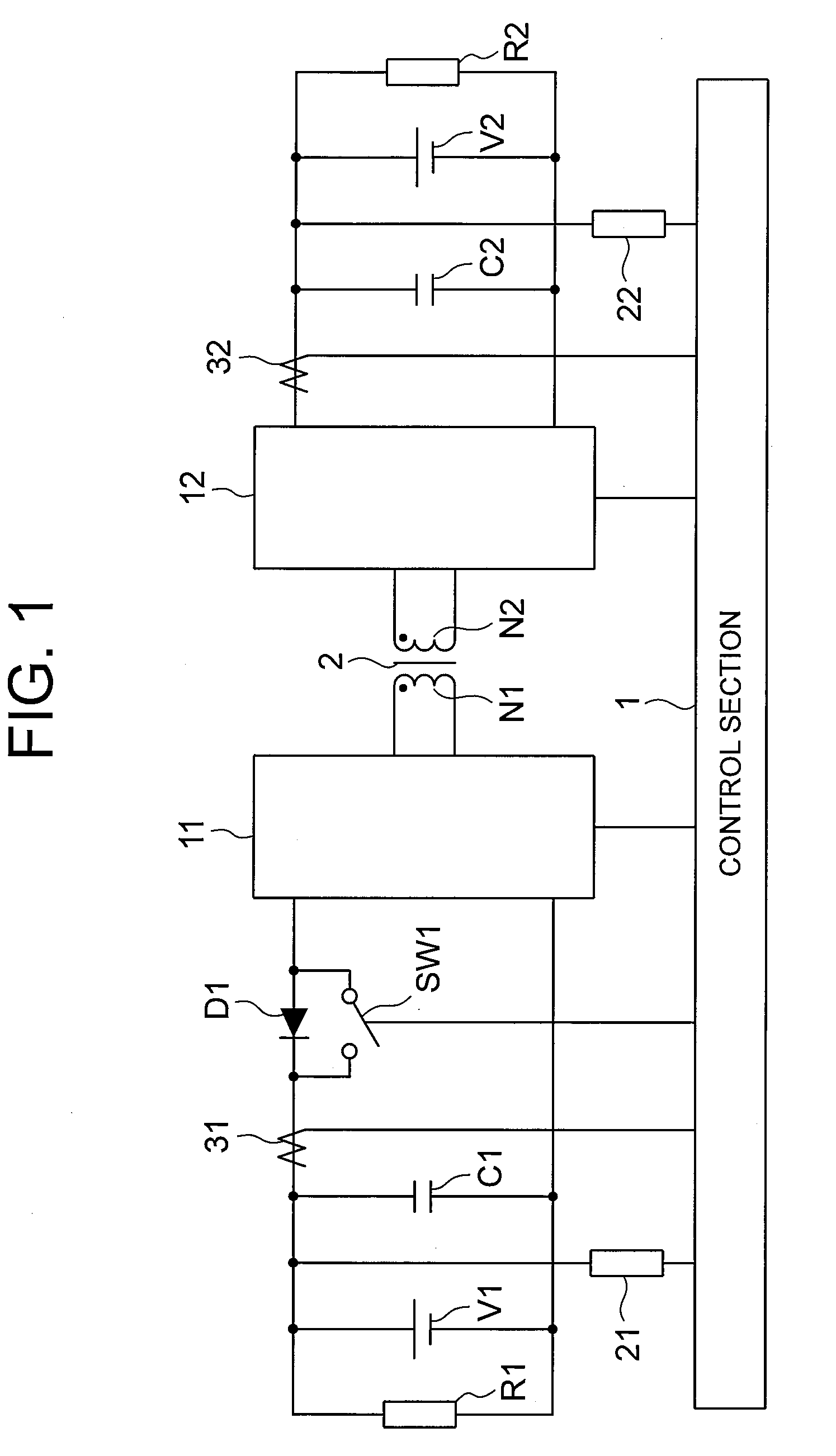
[0036]FIG. 1 is a schematic circuit diagram of a bidirectional DC-DC converter according to a first embodiment of the present invention. The bidirectional DC-DC converter is connected between the DC power supply V1 and the DC power supply V2 to transfer electrical power between the DC power supply V1 and the DC power supply V2. A load R1 is connected to the DC power supply V1, whereas a load R2 is connected to the DC power supply V2.
[0037]Referring to FIG. 1, a smoothing capacitor C1 is connected to the DC power supply V1, whereas a smoothing capacitor C2 is connected to the DC power supply V2. The DC terminals of a switching circuit 11 are connected to the smoothing capacitor C1 through a diode D1. The connection of this diode D1 is oriented so that electrical power flows from the switching circuit 11 to the DC power supply V1 and does not flow from the DC power supply V1 to the switching circuit 11. A switch SW1 is connected in parallel with the diode D1. Further, the DC terminals...
second embodiment
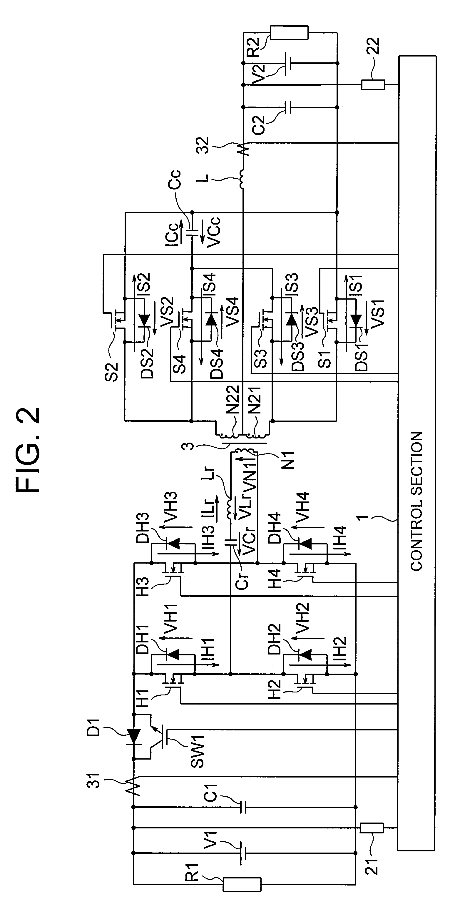
[0047]FIG. 2 is a schematic circuit diagram of a bidirectional DC-DC converter according to a second embodiment of the present invention. The bidirectional DC-DC converter transfers electrical power between a DC power supply V1 and a DC power supply V2, which are connected to opposite ends of the bidirectional DC-DC converter. A load R1 is connected to the DC power supply V1, whereas a load R2 is connected to the DC power supply V2.
[0048]Referring to FIG. 2, a smoothing capacitor C1 is connected to the DC power supply V1, whereas a smoothing capacitor C2 is connected to the DC power supply V2. Switching devices H1, H2 are connected in series with a first switching leg. The first switching leg is connected to the smoothing capacitor C1 through a diode D1. The connection of this diode D1 is oriented so that electrical power flows from the first switching leg to the DC power supply V1 and does not flow from the DC power supply V1 to the first switching leg. A switch SW1 is connected in...
third embodiment
[0106]FIG. 5 is a schematic circuit diagram of a bidirectional DC-DC converter according to a third embodiment of the present invention. The bidirectional DC-DC converter transfers electrical power between a DC power supply V1 and a DC power supply V2, which are connected to opposite ends of the bidirectional DC-DC converter.
[0107]Referring to FIG. 5, a smoothing capacitor C1 is connected to the DC power supply V1, whereas a smoothing capacitor C2 is connected to the DC power supply V2. Switching devices H1 and H2 are connected in series with a first switching leg. The first switching leg is connected to the smoothing capacitor C1 through a diode D1. The connection of this diode D1 is oriented so that electrical power flows from the first switching leg to the DC power supply V1 and does not flow from the DC power supply V1 to the first switching leg. A switch SW1 is connected in parallel with the diode D1. A winding N1, a resonant reactor Lr, and a resonant capacitor Cr are connecte...
PUM
 Abstract
Description
Claims
Application Information
 - R&D
- Intellectual Property
- Life Sciences
- Materials
- Tech Scout
- Unparalleled Data Quality
- Higher Quality Content
- 60% Fewer Hallucinations
Browse by: Latest US Patents, China's latest patents, Technical Efficacy Thesaurus, Application Domain, Technology Topic, Popular Technical Reports.
© 2025 PatSnap. All rights reserved.Legal|Privacy policy|Modern Slavery Act Transparency Statement|Sitemap|About US| Contact US: help@patsnap.com


