Non-contact power transmission device
a power transmission device and non-contact technology, applied in the direction of electric variable regulation, process and machine control, instruments, etc., can solve the problems of transmitters unintentionally providing power to a plurality of receivers, no frequency selectivity for power transmission between power transmitters,
- Summary
- Abstract
- Description
- Claims
- Application Information
AI Technical Summary
Benefits of technology
Problems solved by technology
Method used
Image
Examples
first embodiment
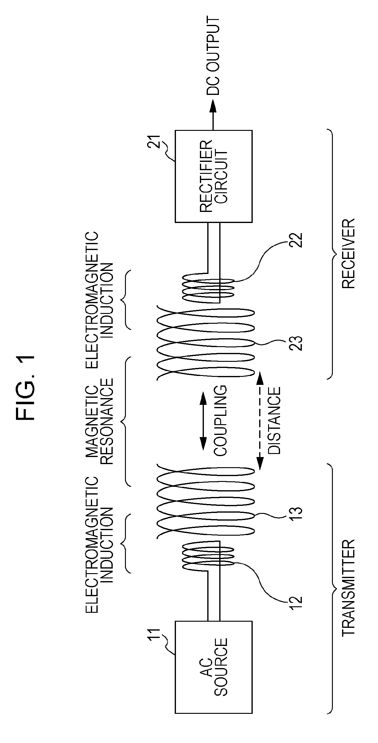
[0037]FIG. 1 illustrates a configuration of a non-contact power transmission device according to the first embodiment of the present invention. The non-contact power transmission device according to the first embodiment has a one-to-one correspondence of a transmitter and a receiver. As illustrated in FIG. 1, the transmitter has an alternating current (AC) source 11, an excitation element 12, and a resonance element 13. The receiver has a rectifier circuit 21, an excitation element 22, and a resonance element 23.
[0038]The excitation elements 12 and 22 and the resonance elements 13 and 23 are each formed of an air-core coil of a wound wire to utilize inductance. The excitation element 12 and the resonance element 13 of the transmitter are strongly coupled by electromagnetic induction. Similarly, the excitation element 22 and the resonance element 23 are strongly coupled by electromagnetic induction.
[0039]The resonance element 13 and the resonance element 23 are disposed at relative p...
second embodiment
[0046]FIG. 5 illustrates a configuration of a non-contact power transmission device according to the second embodiment of present invention. The non-contact power transmission device according to the second embodiment has one transmitter and two receivers. That is, the non-contact power transmission device has a one-to-two correspondence between the transmitter and the receivers.
[0047]The transmitter has an oscillation-frequency variable AC source 31 for applying an alternating current, an excitation element 32, and a resonance element 33 of which the resonant frequency is variable.
[0048]The oscillation-frequency variable AC source 31 is an alternating current source with variable alternating current frequency which supplies an alternating current to the excitation element 32, thereby inducing a current in the resonance element 33 by electromagnetic induction. The frequency of an alternating current generated in the oscillation-frequency variable AC source 31 can be controlled so as...
third embodiment
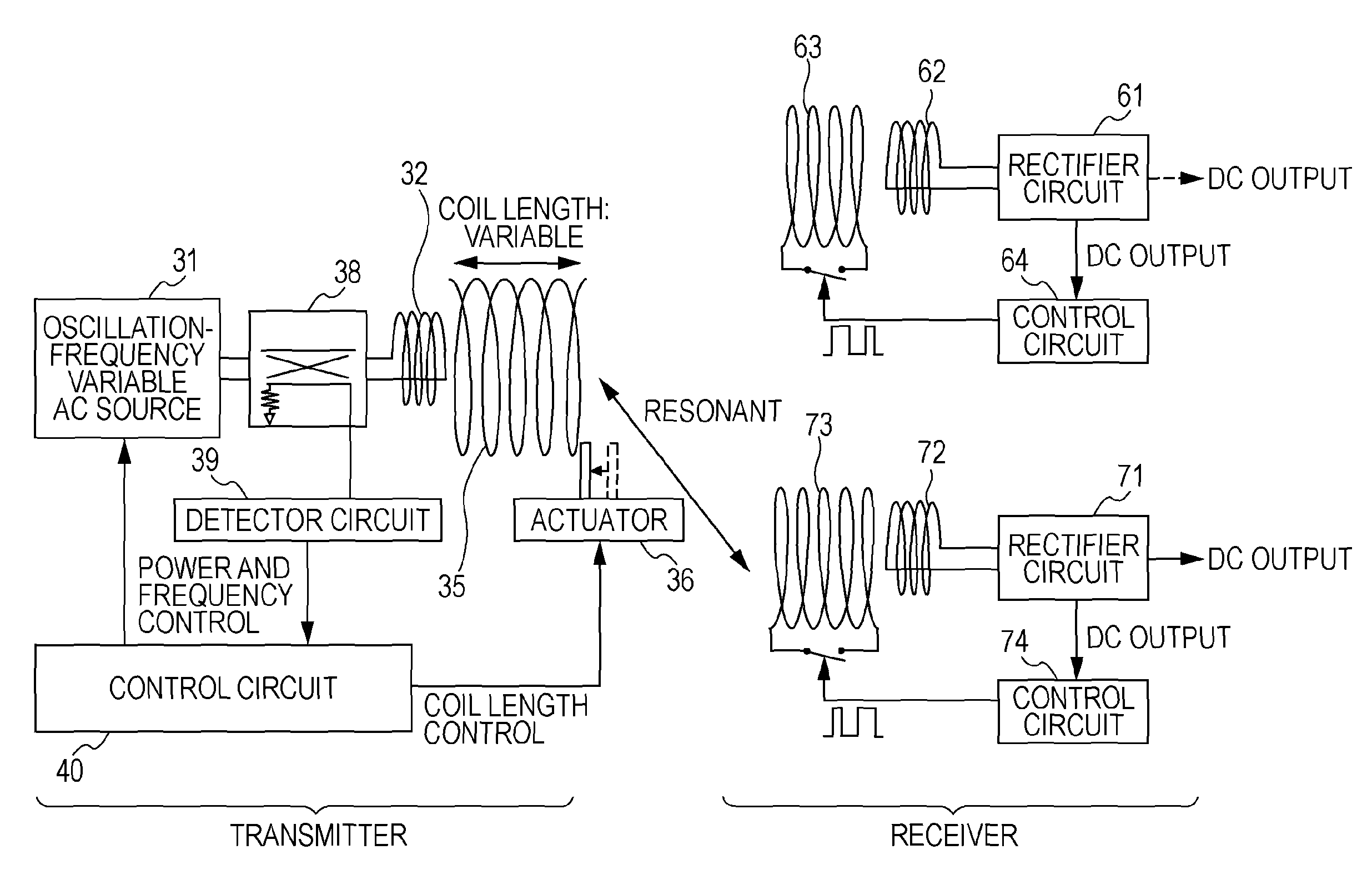
[0060]FIG. 9 illustrates a configuration of a non-contact power transmission device according to the third embodiment of the present invention. In the non-contact power transmission device according to the third embodiment, inductance is varied by changing the entire length of a coil by means of changing the winding pitch without changing the wire length, in order to vary the resonant frequency of the transmitter. Note that components similar to those of non-contact power transmission device of the second embodiment are designated by the same reference numerals used in the second embodiment, and thus the detailed description thereof will be omitted.
[0061]A transmitter has an oscillation-frequency variable AC source 31 for applying an alternating current, an excitation element 32, and a resonance element 35 of which the resonant frequency is variable.
[0062]The oscillation-frequency variable AC source 31 is an alternating current source with variable alternating current frequency and ...
PUM
| Property | Measurement | Unit |
|---|---|---|
| diameter | aaaaa | aaaaa |
| diameter | aaaaa | aaaaa |
| length | aaaaa | aaaaa |
Abstract
Description
Claims
Application Information
 - R&D
- Intellectual Property
- Life Sciences
- Materials
- Tech Scout
- Unparalleled Data Quality
- Higher Quality Content
- 60% Fewer Hallucinations
Browse by: Latest US Patents, China's latest patents, Technical Efficacy Thesaurus, Application Domain, Technology Topic, Popular Technical Reports.
© 2025 PatSnap. All rights reserved.Legal|Privacy policy|Modern Slavery Act Transparency Statement|Sitemap|About US| Contact US: help@patsnap.com


