
Corrosion resistant faucets with components made of different metallic materials

a technology of corrosion resistance and faucets, applied in the field of faucets, can solve the problems of differences in electrical properties between metals, high material cost of brass, and high cost of brass, and achieve the effect of avoiding galvanic corrosion and low additional cos

Active Publication Date: 2013-02-19
KOHLER CO
View PDF18 Cites 10 Cited by
  • Summary
  • Abstract
  • Description
  • Claims
  • Application Information

AI Technical Summary

Benefits of technology

[0027](b) the side cavity defines a second key compatible with the first key such that rotation of the insulator sleeve within the outer housing can be restricted thereby;
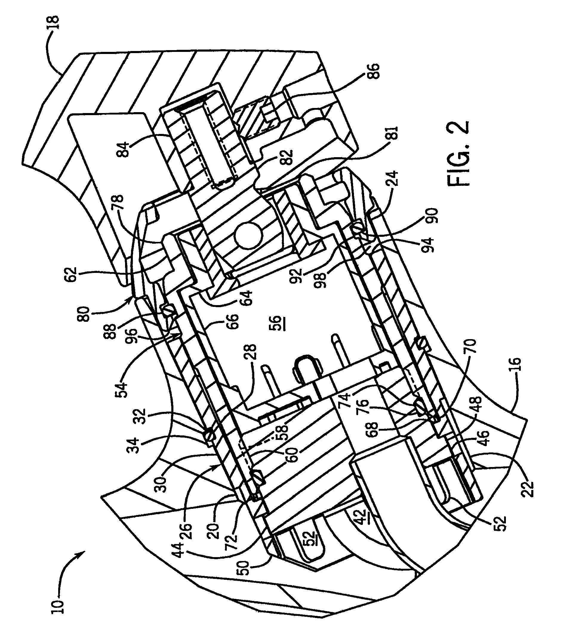
[0031]It should be appreciated that the present invention permits the use of a relatively inexpensive outer decorative material for the main faucet housing (such as zinc), while permitting one to continue to use the preferred brass for the collar that traps the valve cartridge. An insulating structure is provided at relatively low additional cost that avoids the galvanic corrosion which would otherwise normally occur if the brass collar were in long term contact with the outer housing.

Problems solved by technology

However, the material cost of brass can be high, making it desirable to find alternative materials for at least some of the larger faucet parts.
However, such zinc-based surfaces are susceptible to corrosion where they contact internal brass components long term.
In this regard, when a zinc-based surface is in constant contact with brass, particularly in a wet or humid environment, the differences in electrical properties between the metals can lead to galvanic corrosion.
This can undermine the structural integrity of the housing or alter its decorative appearance.
While one could make all internal components of a plastic or even zinc, this would lead to other concerns such as long term reliability and / or strength.

Method used


Image

  • Corrosion resistant faucets with components made of different metallic materials
  • Corrosion resistant faucets with components made of different metallic materials
  • Corrosion resistant faucets with components made of different metallic materials

Examples


Embodiment Construction

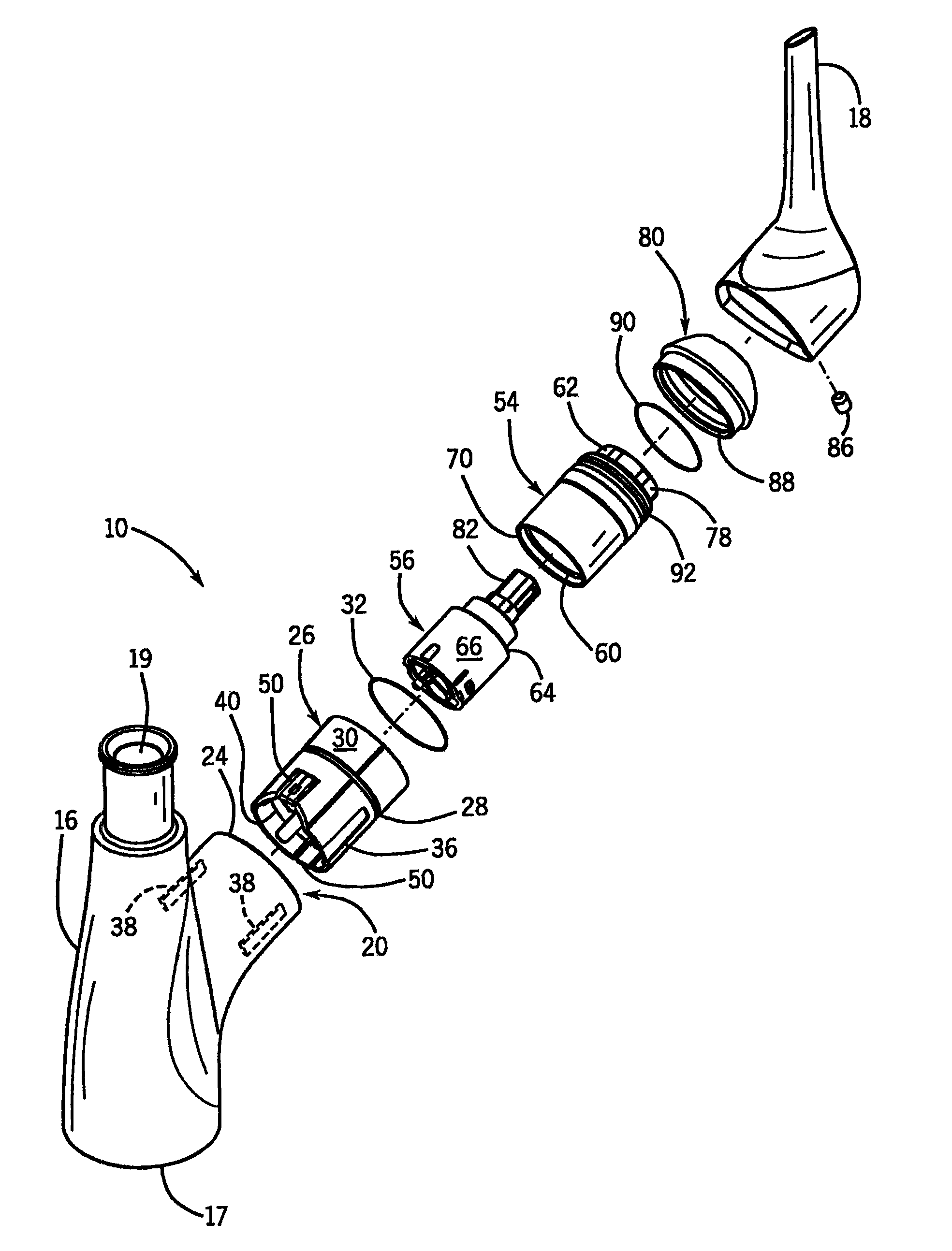
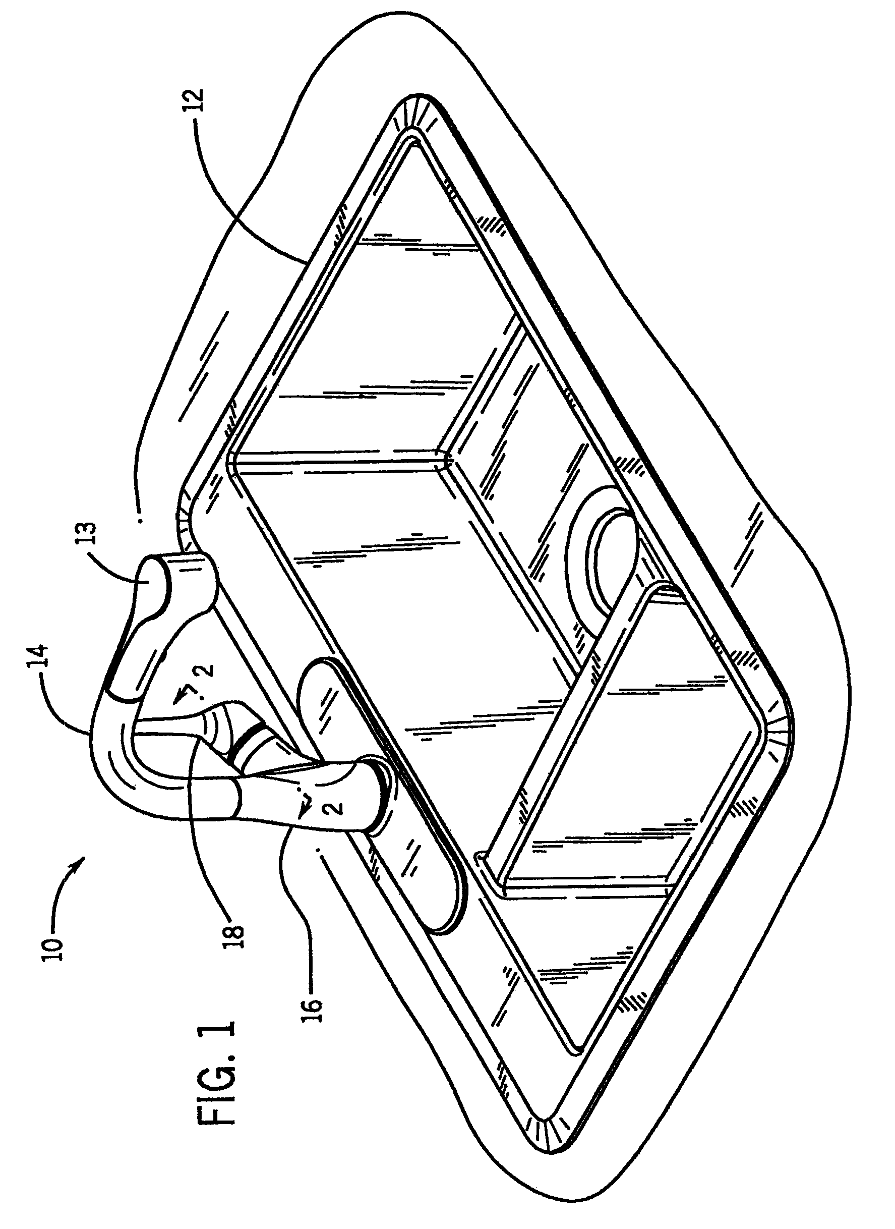
[0037]An example faucet 10 is shown in FIG. 1 mounted on a conventional kitchen sink 12. It should be appreciated that the term “faucet” is being used in this patent in its broadest sense to cover a wide range of plumbing fittings where water volume and / or temperature is controlled by the fitting adjacent a spout. Thus, it should be interpreted to cover kitchen or bathroom faucets, as well as tub fillers having associated control valving, shower heads having associated control valving, etc.

[0038]Faucet 10 is in the form of a kitchen pull-out spray type faucet having a spout 14 extending upward from main outer housing 16. There is a control handle 18 at the side of the faucet to control the flow volume and temperature of water directed out of the outer housing 16 through the spout 14, to an associated pull-out spray head 13.

[0039]The outer housing 16 is preferably made of zinc, or a zinc alloy of 50% or more zinc. Alternatively, it could be a base material plated with such a zinc-bas...


PUM


Abstract

A faucet is disclosed which has an outer housing formed of zinc which has a lower entry, an upper outlet, and a side cavity. There is a supply line structure extendible from the lower entry into or adjacent the side cavity, and a valve cartridge positioned in the side cavity. A plastic insulator sleeve is positioned in the side cavity between a wall of the outer housing and the valve cartridge. A brass collar is nested within the insulator sleeve and positioned outside of the valve cartridge. Hence, the advantages of a zinc outer housing are achieved while avoiding galvanic corrosion due to contact between brass and zinc surfaces. The insulator sleeve also facilitates rotational and axial alignment, and sealing.

Description

CROSS-REFERENCE TO RELATED APPLICATION[0001]This application claims priority based on U.S. provisional application 61 / 176,516 filed May 8, 2009.STATEMENT OF FEDERALLY SPONSORED RESEARCH OR DEVELOPMENT[0002]Not applicable.BACKGROUND OF THE INVENTION[0003]The present invention relates to faucets with an outer main housing having a surface made of one metallic composition and at least one adjacent component having a surface made of another metallic composition. More particularly it relates to structures that can avoid galvanic corrosion which could otherwise occur if the two surfaces were in contact with each other after assembly of the faucet.[0004]A typical faucet includes an outer housing made of brass, as well as many internal brass parts. Brass is a preferred material for these purposes due to its appearance, durability, strength, machinability, and ability to support a variety of finishes. However, the material cost of brass can be high, making it desirable to find alternative ma...

Claims


Application Information

Patent Timeline
Patent Type & Authority Patents(United States)
IPC IPC(8): F16K21/00E03C1/04
CPCE03C1/0404E03C1/04Y10T137/598Y10T137/9464
Inventor ESCHE, JOHN C.RADDER, STEVEN T.
Owner KOHLER CO
Learn More