
Image processing method and image processing system

a processing method and image processing technology, applied in the direction of picture signal generators, instruments, solid-state device signal generators, etc., can solve the problems of troublesome calculation, heavy load on the system, and inability to process video streams instantly, so as to shorten the image processing time and simplify the flow path

Active Publication Date: 2013-02-12
ASUSTEK COMPUTER INC
View PDF29 Cites 3 Cited by
  • Summary
  • Abstract
  • Description
  • Claims
  • Application Information

AI Technical Summary

Benefits of technology

This approach enables faster image processing by adjusting luminance and chrominance in a single flow path, reducing the computational burden and improving processing speed, especially for YCbCr 4:2:2 and 4:2:0 formats.

Problems solved by technology

Therefore, additional color space conversion is a load to the system, and the video stream cannot be processed instantly.
However, in each image processing flow path, each component (Y, Cb or Cr) in the image information are adjusted according to the luminance lookup table or the chrominance LUT, and that means the components need to be calculated for three times. Therefore, the troublesome calculation is a heavy load to the system without independent image processor.

Method used


Image

  • Image processing method and image processing system
  • Image processing method and image processing system
  • Image processing method and image processing system

Examples


Embodiment Construction

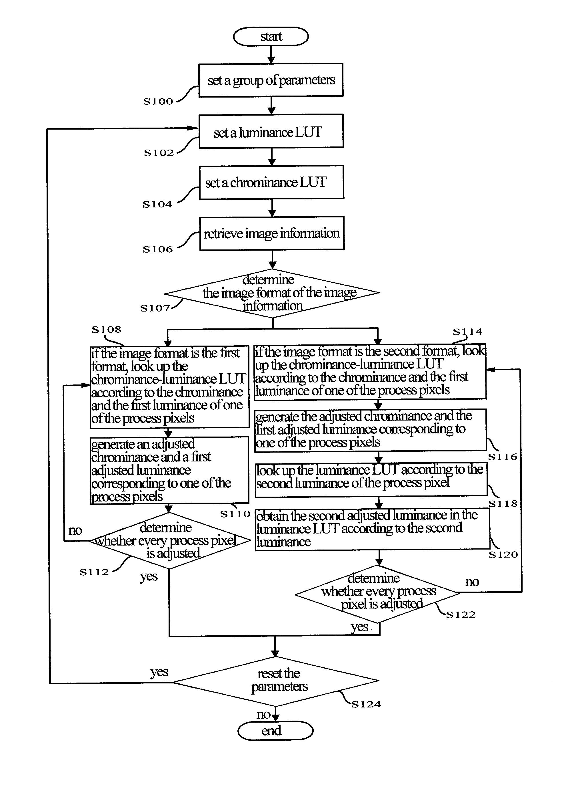
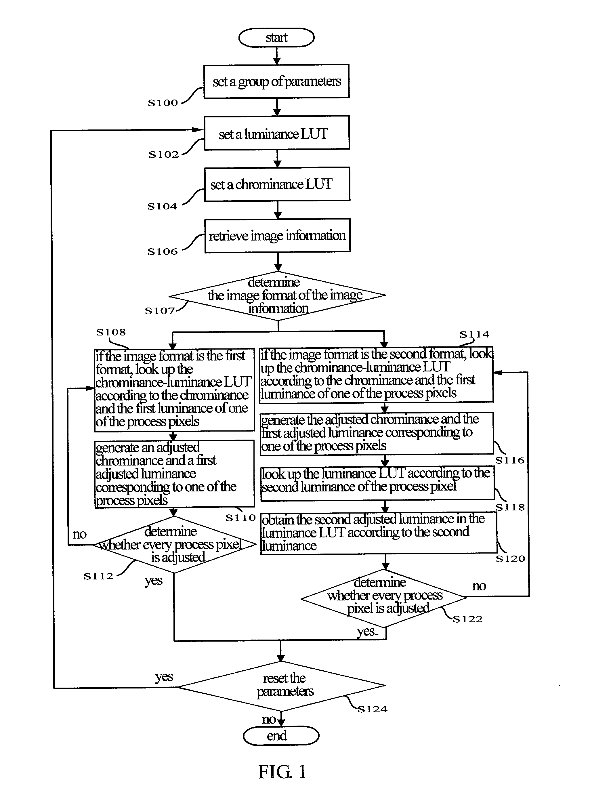
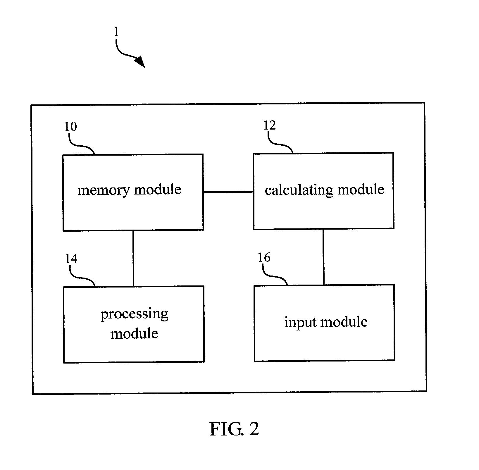
[0018]FIG. 1 is a flow chart diagram showing the image processing method in an embodiment of the invention. FIG. 2 is a functional diagram showing the image processing system 1 which can perform the image processing method in an embodiment of the invention. The image processing method and the image processing system are adapted to processing image information (such as an image, a multi-media movie or a video stream). The image information has a format of the image. As shown in FIG. 2, in the embodiment, the image processing system 1 includes a memory module 10, a calculating module 12, a processing module 14 and an input module 16. The calculating module 12 and the processing module 14 are electrically connected to the memory module 10, respectively. The input module 16 is electrically connected to the calculating module 12. The memory module 10 stores the image information including multiple process pixels.

[0019]In the embodiment, the image processing method and the image processin...


PUM


Abstract

An image processing method and an image processing system adapted to processing image information with multiple process pixels are disclosed. The image processing method includes steps of: setting a group of parameters; establishing a luminance lookup table; establishing a chrominance-luminance lookup table; retrieving the image information; determining a format of the image information; and if the format of the image is a first format, utilizing the chrominance-luminance lookup table to generate an adjusted chrominance and a first adjusted luminance corresponding to one of the process pixels; if the format of the image is a second format, utilizing the chrominance-luminance lookup table and the luminance lookup table to generate an adjusted chrominance, a first adjusted luminance, and a second adjusted luminance corresponding to one of the process pixels.

Description

CROSS REFERENCE TO RELATED APPLICATIONS[0001]This Non-provisional application claims priority under 35 U.S.C. §119(a) on patent application No(s). 098119635 filed in Taiwan, Republic of China on Jun. 12, 2009, the entire contents of which are hereby incorporated by reference.BACKGROUND OF THE INVENTION[0002]1. Field of Invention[0003]The invention relates to an image processing method and an image processing system and, more particularly, to an image processing method and an image processing system performed by a looking up table (chrominance-luminance lookup table, luminance lookup table).[0004]2. Related Art[0005]With the progress of digital image display techniques, electronic display devices with high definition, high stableness, and multi-functions are widely used in people's daily life. Digital electronic devices such as a liquid crystal display (LCD) screen, a plasma display and a projector become to be main media in people's life for getting information or communicating with...

Claims


Application Information

Patent Timeline
Patent Type & Authority Patents(United States)
IPC IPC(8): G06K9/40
CPCH04N1/6005H04N1/6027H04N9/045
Inventor TSAI, CHI YI
Owner ASUSTEK COMPUTER INC
Learn More