Light emitting device
a light-emitting device and light-emitting technology, which is applied in the field ofstroboscopic light-emitting devices, can solve the problems of difficult treatment of the curved surface of the reflector, disorder in the light distribution (orientation) characteristic at the joint part, and the prone shape of the reflector, so as to suppress local suppress the disorder in the light distribution characteristi
- Summary
- Abstract
- Description
- Claims
- Application Information
AI Technical Summary
Benefits of technology
Problems solved by technology
Method used
Image
Examples
examples 1 to 7
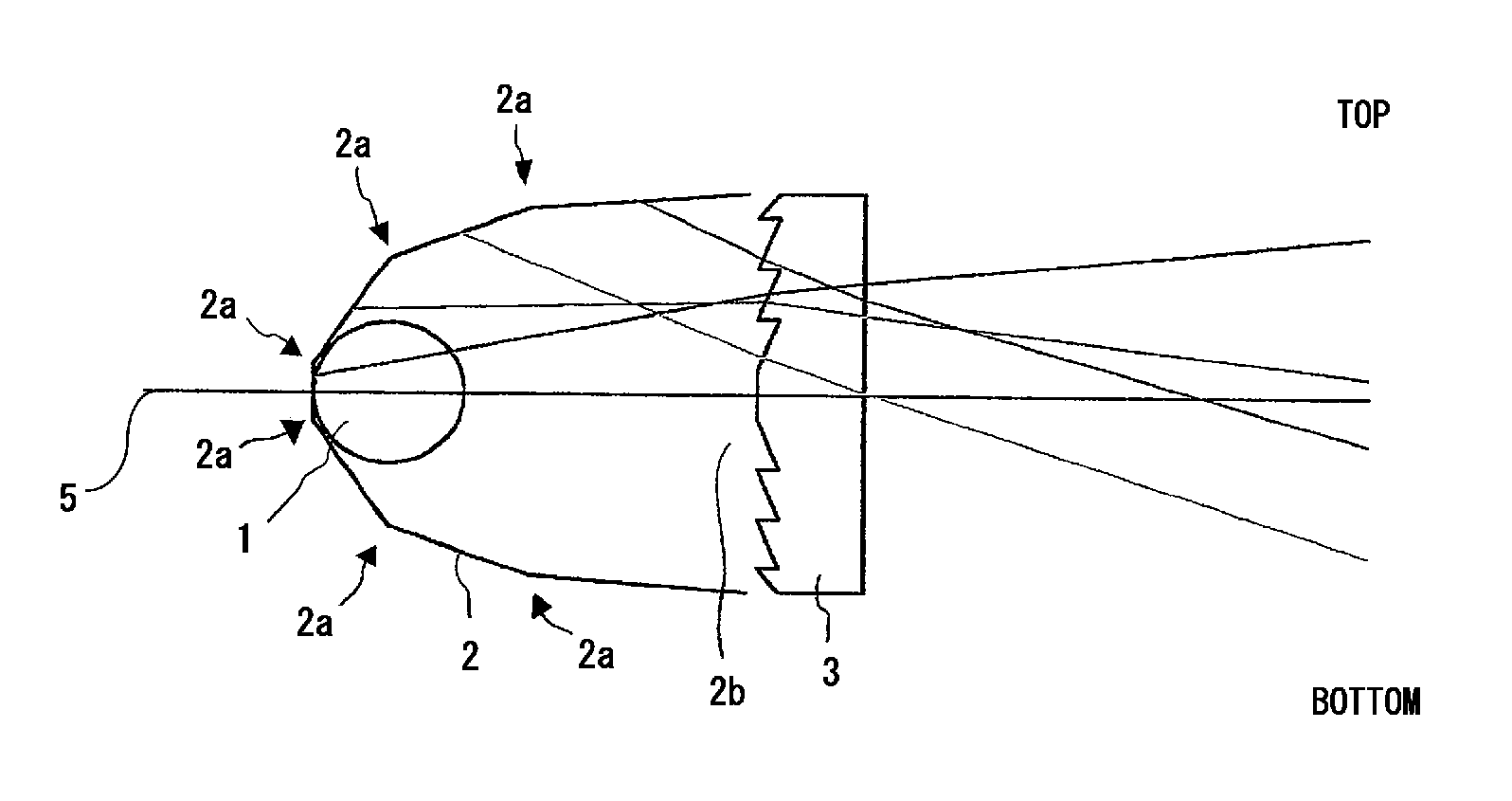
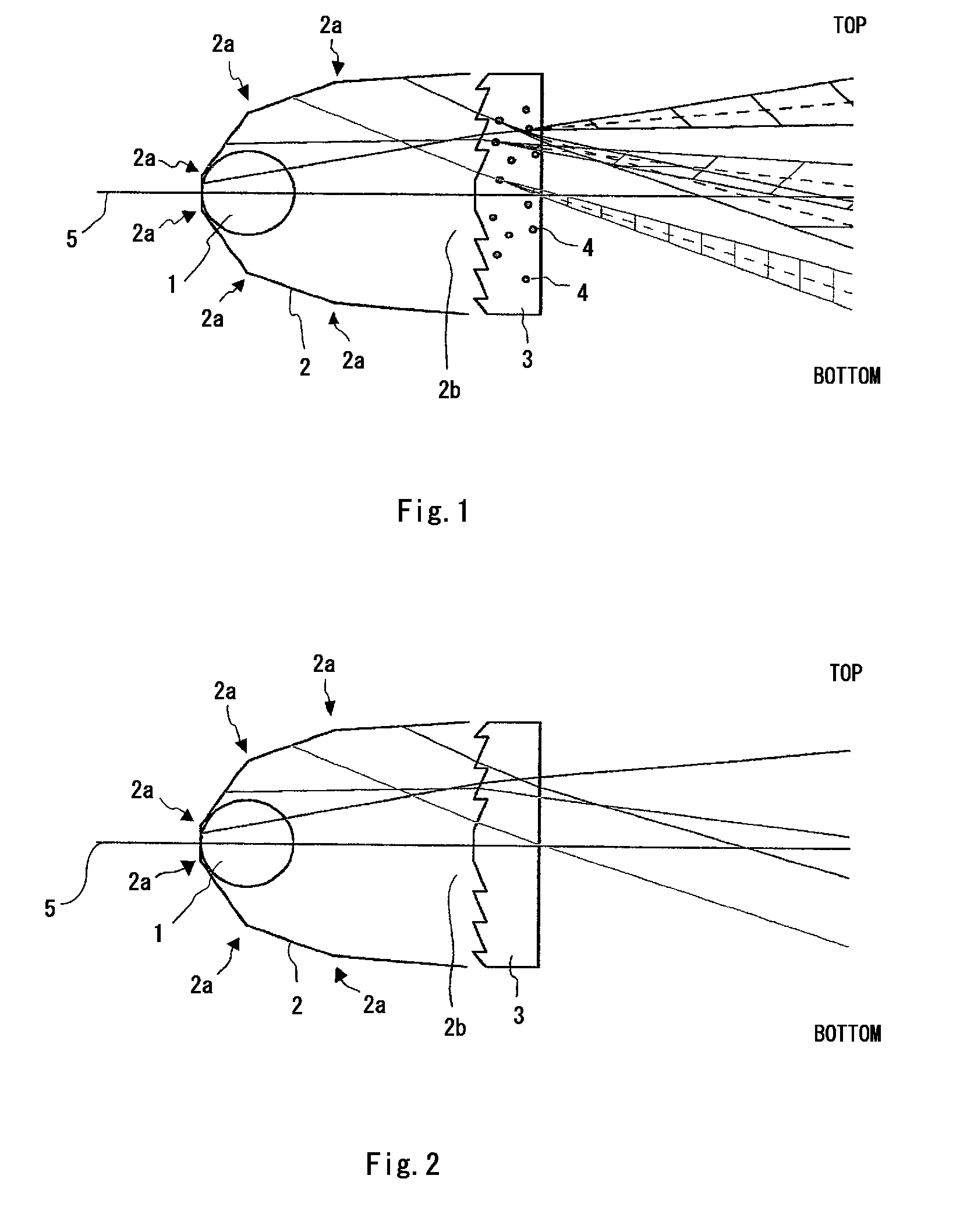
[0048]Lens 3 according to each of example 1 to example 7 was produced as the following. In the examples 1 to 7, a methacrylic resin was used as a base material, and crosslinked MS type particles were added as the filler 4, the particle being a product of Sekisui Plastics Co. Ltd., XX51F, and approximately 5 μm in mean particle size. The additive amount of the filler 4 was changed for each of the examples 1 to 7, and it was set to 0.1 parts by weight, 0.3 parts by weight, 0.5 parts by weight, 1.0 parts by weight, 1.5 parts by weight, 2.0 parts by weight, 3.0 parts by weight, for the respective examples, per 100 parts by weight of the base material.
[0049]Furthermore, an ultraviolet absorbent (a product of Shipro Kasei Kaisha, Ltd., seesorb 703) was added to the base material, in addition to the filler 4.
[0050]A production method will be explained briefly. By using a drum blender, a predetermined amount of filler 4 and 0.51 parts by weight of ultraviolet absorbent (a product of Shipro ...
examples 8 to 11
[0063]Lens 3 according to each of example 8 to example 11 was produced as the following. In the examples 8 to 11, a methacrylic resin with refractive index 1.49 was used as the base material, and as the filler 4, fluorine type fine particles with refractive index 1.3, alumina fine particles with refractive index 1.7, barium sulfide fine particles with refractive index 2.0, and titanium oxide fine particles with refractive index 2.8 were added, respectively.
[0064]The mean particle size of the filler 4 was set to 5 μm in any of the examples. Moreover, the additive amount of the filler 4 was set to 0.75 parts by weight per 100 parts by weight of the base material, in any of the examples 8 to 11. An ultraviolet absorbent (product of Shipro Kasei Kaisha, Ltd., seesorb 703) was also added to the base material, in addition to the filler 4. The method for producing the lens 3 was the same as the example 1.
examples 12 to 19
[0072]Lens 3 according to each of the examples 12 to 19 was produced as the following. In the examples 12 to 19, a methacrylic resin was used as the base material, and crosslinked MS type particles (product of Sekisui Plastics Co. Ltd., XX51F) were added as the filler 4. The mean particle size of the filler 4 was changed in each of the examples 12 to 19, and they were 0.1 μm, 0.3 μm, 0.5 μm, 1.0 μm, 7.0 μm, 10 μm, 15 μm, and 20 μm, respectively.
[0073]The additive amount of the filler 4 was set to 0.75 parts by weight per 100 parts by weight of the base material, in any of the examples 12 to 19. The ultraviolet absorbent (product of Shipro Kasei Kaisha, Ltd., seesorb 703) was added to the base material, in addition to the filler 4. The production method of the lens 3 was the same as that of example 1.
PUM
 Abstract
Description
Claims
Application Information
 - R&D
- Intellectual Property
- Life Sciences
- Materials
- Tech Scout
- Unparalleled Data Quality
- Higher Quality Content
- 60% Fewer Hallucinations
Browse by: Latest US Patents, China's latest patents, Technical Efficacy Thesaurus, Application Domain, Technology Topic, Popular Technical Reports.
© 2025 PatSnap. All rights reserved.Legal|Privacy policy|Modern Slavery Act Transparency Statement|Sitemap|About US| Contact US: help@patsnap.com


