
Light emitting device

a light-emitting device and light-emitting technology, which is applied in the field ofstroboscopic light-emitting devices, can solve the problems of difficult treatment of the curved surface of the reflector, disorder in the light distribution (orientation) characteristic at the joint part, and the prone shape of the reflector, so as to suppress local suppress the disorder in the light distribution characteristi

Active Publication Date: 2009-09-03
STANLEY ELECTRIC CO LTD
View PDF5 Cites 2 Cited by
  • Summary
  • Abstract
  • Description
  • Claims
  • Application Information

AI Technical Summary

Benefits of technology

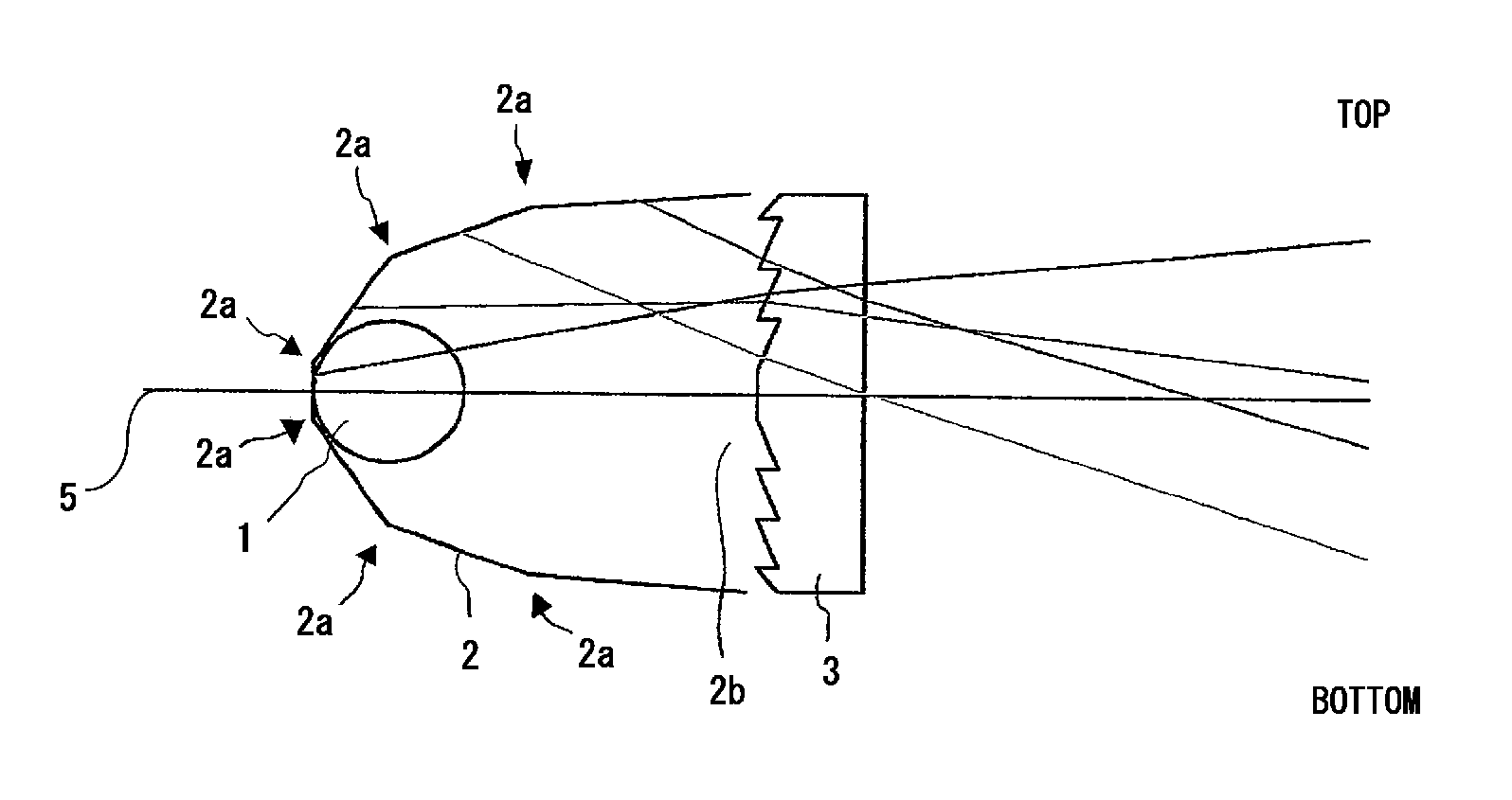
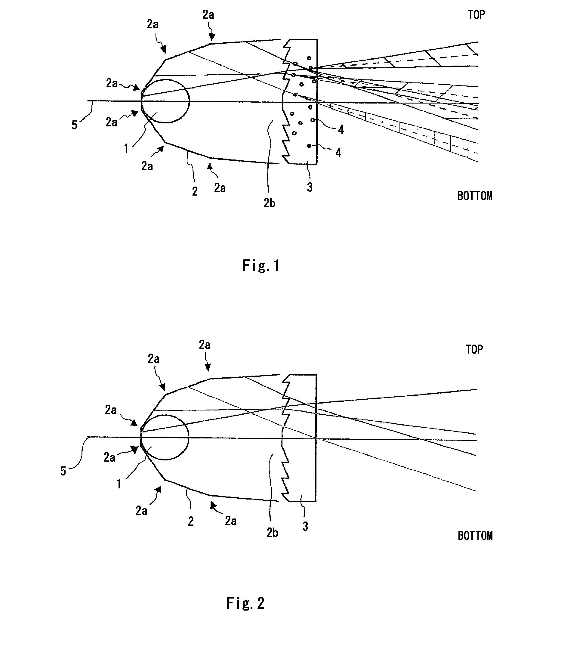
The present invention relates to a strobe apparatus that includes an illuminator, a reflector for reflecting light from the illuminator, and a lens for allowing passage of the light reflected by the reflector to illuminate outwardly. The lens contains a base material and a filler in the base material. The filler causes a scattering of passing light appropriately, which suppresses local disorder in a light distribution characteristic, even though the reflector includes bends. The invention allows for easy production of a small-sized stroboscopic light emitting device.

Problems solved by technology

In particular, in the case of a stroboscopic light emitting device built in a camera, being small in aperture diameter such as equal to or less than 1 cm, for instance, it is difficult to treat the curved surface of the reflector.
In this case here, the curved surface is approximated by a small number of surfaces, and therefore, the reflector is prone to have a shape being bent on a large scale at each joint between the surfaces.
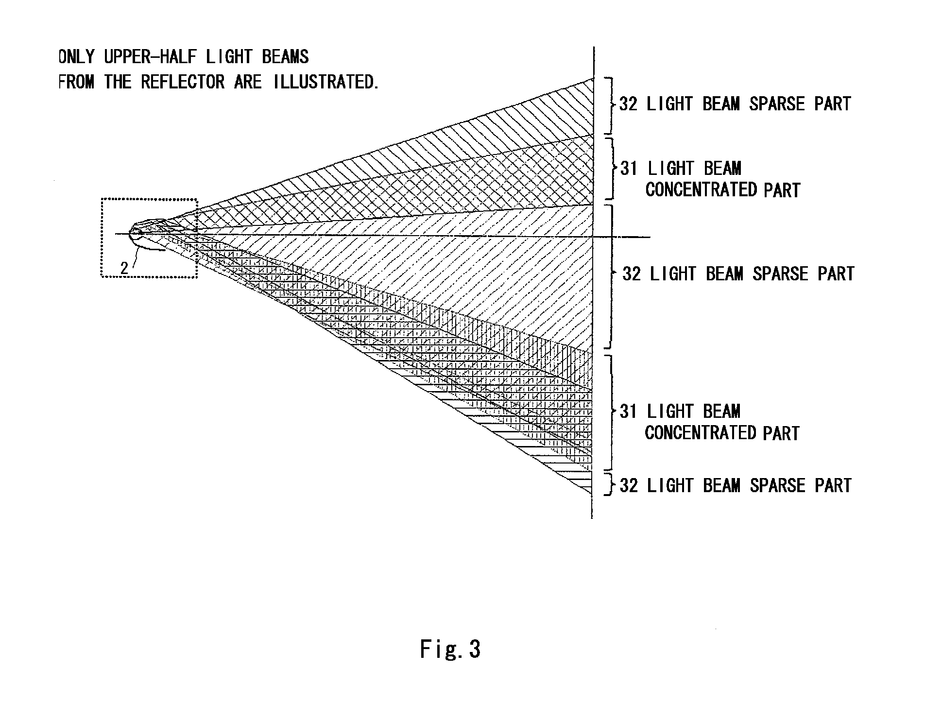
Consequently, at each joint between the surfaces, the direction of the reflected light beams emitted from the illuminator varies in a discontinuous manner, and this may cause disorder in light distribution (orientation) characteristic at the joint part.
If photographing is carried out using a strobe with such disordered light distribution (orientation) characteristic, a distribution of light quantity illuminated on the photographic subject is impaired, thereby damaging an image quality.

Method used


Image

  • Light emitting device
  • Light emitting device
  • Light emitting device

Examples


examples 1 to 7

[0048]Lens 3 according to each of example 1 to example 7 was produced as the following. In the examples 1 to 7, a methacrylic resin was used as a base material, and crosslinked MS type particles were added as the filler 4, the particle being a product of Sekisui Plastics Co. Ltd., XX51F, and approximately 5 μm in mean particle size. The additive amount of the filler 4 was changed for each of the examples 1 to 7, and it was set to 0.1 parts by weight, 0.3 parts by weight, 0.5 parts by weight, 1.0 parts by weight, 1.5 parts by weight, 2.0 parts by weight, 3.0 parts by weight, for the respective examples, per 100 parts by weight of the base material.

[0049]Furthermore, an ultraviolet absorbent (a product of Shipro Kasei Kaisha, Ltd., seesorb 703) was added to the base material, in addition to the filler 4.

[0050]A production method will be explained briefly. By using a drum blender, a predetermined amount of filler 4 and 0.51 parts by weight of ultraviolet absorbent (a product of Shipro ...

examples 8 to 11

[0057]Lens 3 according to each of example 8 to example 11 was produced as the following. In the examples 8 to 11, a methacrylic resin with refractive index 1.49 was used as the base material, and as the filler 4, fluorine type fine particles with refractive index 1.3, alumina fine particles with refractive index 1.7, barium sulfide fine particles with refractive index 2.0, and titanium oxide fine particles with refractive index 2.8 were added, respectively.

[0058]The mean particle size of the filler 4 was set to 5 μm in any of the examples. Moreover, the additive amount of the filler 4 was set to 0.75 parts by weight per 100 parts by weight of the base material, in any of the examples 8 to 11. An ultraviolet absorbent (product of Shipro Kasei Kaisha, Ltd., seesorb 703) was also added to the base material, in addition to the filler 4. The method for producing the lens 3 was the same as the example 1.

examples 12 to 19

[0064]Lens 3 according to each of the examples 12 to 19 was produced as the following. In the examples 12 to 19, a methacrylic resin was used as the base material, and crosslinked MS type particles (product of Sekisui Plastics Co. Ltd., XX51F) were added as the filler 4. The mean particle size of the filler 4 was changed in each of the examples 12 to 19, and they were 0.1 μm, 0.3 μm, 0.5 μm, 1.0 μm, 7.0 μm, 10 μm, 15 μm, and 20 μm, respectively.

[0065]The additive amount of the filler 4 was set to 0.75 parts by weight per 100 parts by weight of the base material, in any of the examples 12 to 19. The ultraviolet absorbent (product of Shipro Kasei Kaisha, Ltd., seesorb 703) was added to the base material, in addition to the filler 4. The production method of the lens 3 was the same as that of example 1.


PUM


Abstract

The present invention is directed to a small-sized stroboscopic light emitting device that controls disorder in light distribution (orientation) characteristic caused by a shape of the reflector, and achieves a homogeneous light quantity distribution. The stroboscopic light emitting device includes an illuminator 1, a reflector 2 for reflecting light from the reflector, and a lens 3 for allowing the light reflected by the reflector 2 to pass through and illuminate outwardly, and the lens 3 contains a filler 4 in the base material. A refractive index and a mean particle size of the filler are between or equal to 1.3 to 2.8 and between or equal to 0.1 μm to 20 μm, respectively, and the filler is contained in the base material at the rate between or equal to 0.1 parts by weight to 3.0 parts by weight, per 100 parts by weight of the base material. Since the filler diffuses the passing light adequately, even though the reflector is provided with a bend, local disorder in light distribution (orientation) characteristic caused by the bend can be suppressed.

Description

FIELD OF THE INVENTION[0001]This application claims priority under 35 U.S.C. § 119 to Japanese Patent Application No. 2008-048260, filed Feb. 28, 2008, the entirety of which is incorporated by reference herein.[0002]The present invention relates to a stroboscopic light emitting device, and more particularly, it relates to a stroboscopic light emitting device with a light emitting part that is small in aperture diameter.DESCRIPTION OF THE RELATED ART[0003]The stroboscopic light emitting device has a configuration in which light from an illuminator such as a xenon (Xe) tube, is reflected forward by a reflector, as described in the Japanese Utility Model (Registration) Application Laid-Open Publication No. 2-62425, for instance. The reflector is formed in such a manner as covering the illuminator from the rear side, and from the four side surfaces of left, right, top and bottom. A lens is disposed at an opening forward of the reflector. The lens refracts light beams into the optical di...

Claims


Application Information

Patent Timeline
Patent Type & Authority Applications(United States)
IPC IPC(8): F21V7/00F21V7/07
CPCG03B15/05G03B15/02G03B2215/0525G03B2215/0535
Inventor TAMAKI, YUJIHIOKI, TATSUYASUGIMOTO, EIICHIGOTO, TATSUYAKOBAYASHI, NOBUHIRO
Owner STANLEY ELECTRIC CO LTD
Learn More