
Permanent magnet having improved field quality and apparatus employing the same

a permanent magnet and field quality technology, applied in the field of permanent magnets having improved field quality and apparatus, can solve the problems of increasing precision requirements, increasing cost, and increasing the size and weight of magnets, so as to improve the field and strength of field, reduce size and weight, and improve the effect of precision

Inactive Publication Date: 2013-02-05
MONITOR INSTR
View PDF8 Cites 3 Cited by
  • Summary
  • Abstract
  • Description
  • Claims
  • Application Information

AI Technical Summary

Benefits of technology

The present invention aims to provide an improved permanent magnet with better field uniformity and strength. Additionally, it seeks to offer a magnet design that is smaller and lighter, and a manufacturing process that is less costly.

Problems solved by technology

Though new magnetic materials offered many opportunities to reduce size and weight, the increased requirements in precision on the other hand practically outweigh these benefits.
Today's magnets often are still big in size and weight, and precision (mostly uniformity) is always an issue.
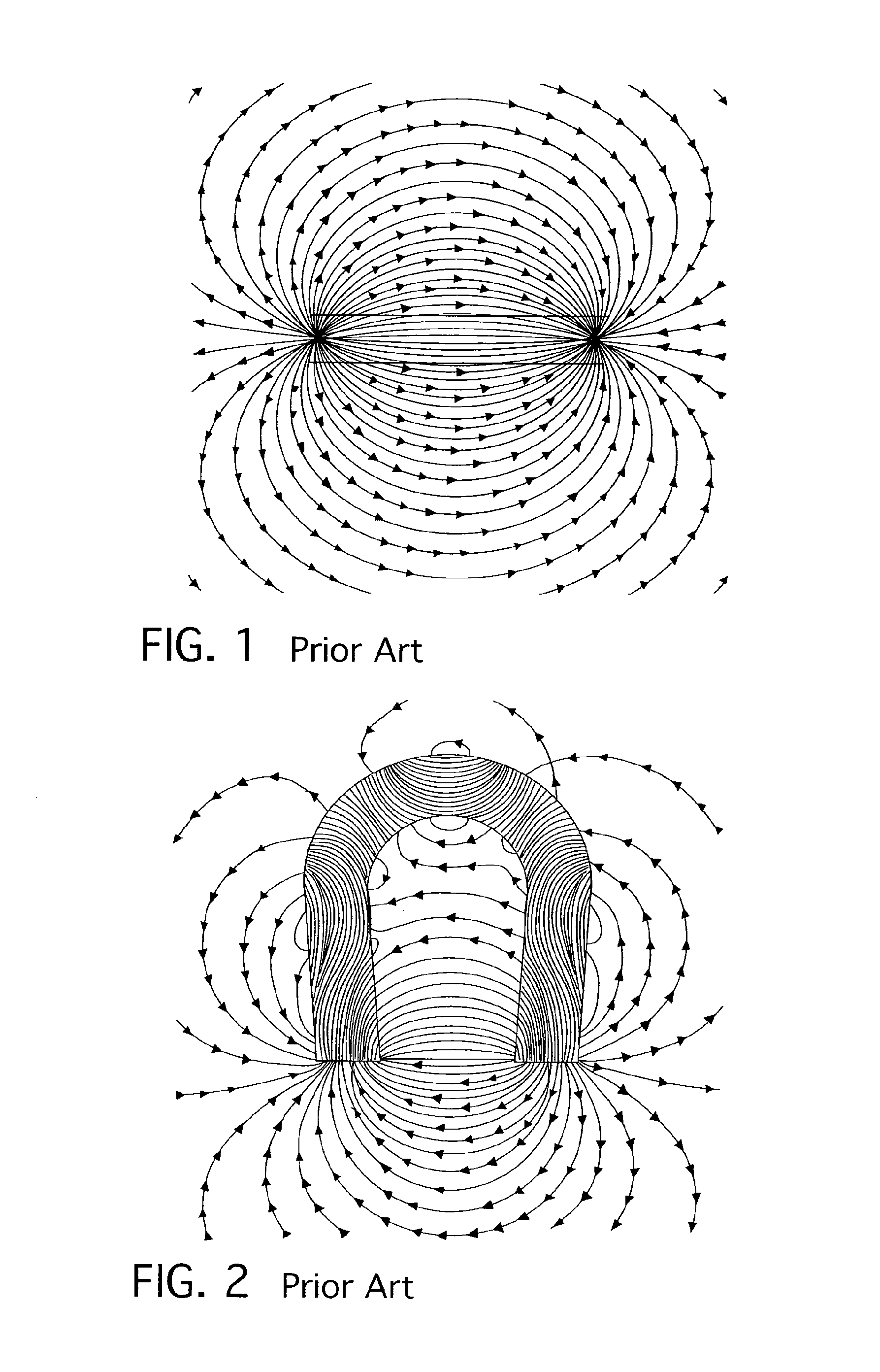
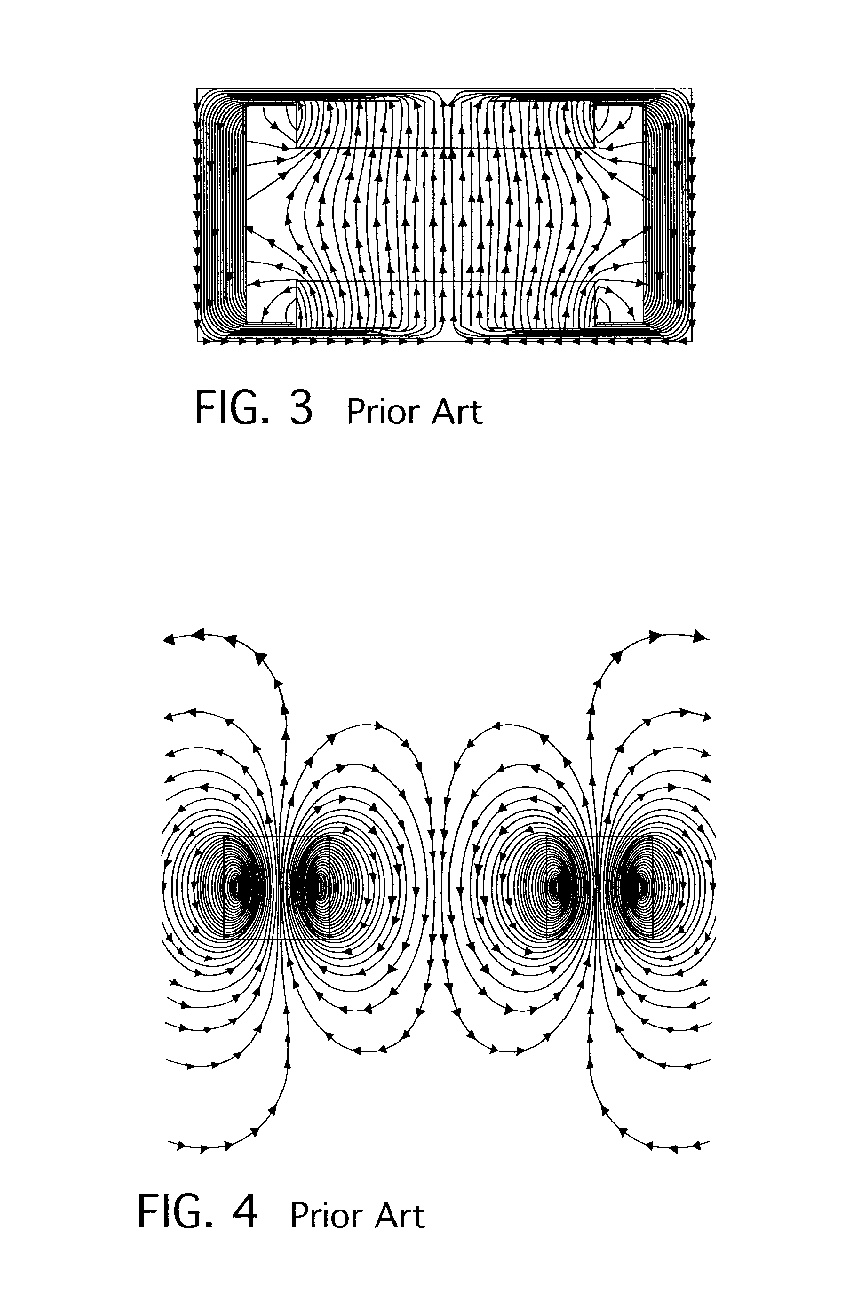
Carefully shaped pole pieces can reduce the effect of fringing fields and extend the area of useful uniformity, but they cannot eliminate the fringing fields in principle.

Method used


Image

  • Permanent magnet having improved field quality and apparatus employing the same
  • Permanent magnet having improved field quality and apparatus employing the same
  • Permanent magnet having improved field quality and apparatus employing the same

Examples


Embodiment Construction

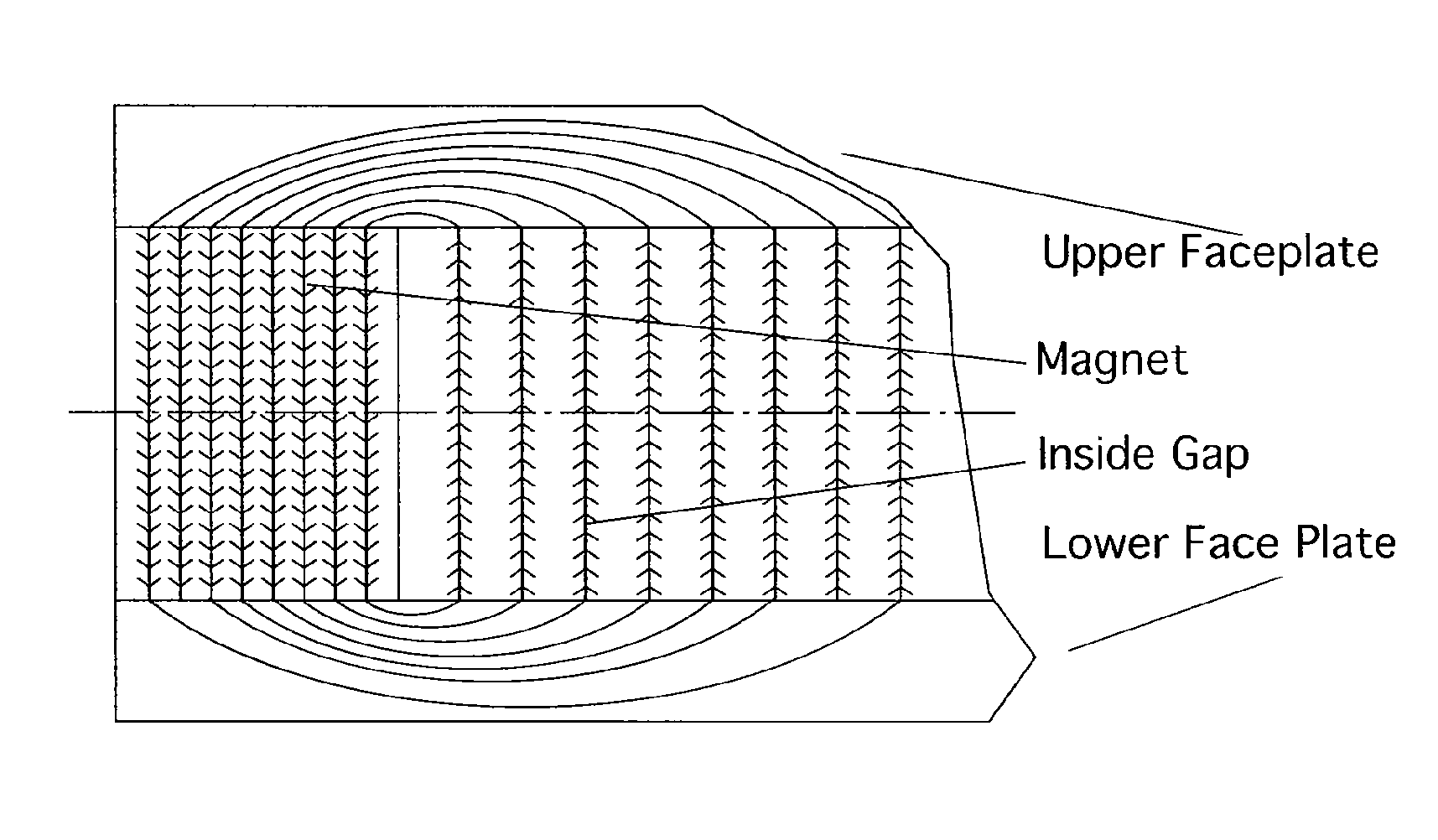
[0029]A magnet design is described to generate strong, uniform fields inside a cylindrical volume. Compared to common designs used for dipole magnets the torus shape introduced here simplifies manufacturing processes and reduces the number of parts required. The choice of this geometry provides better uniformity and higher field strength than achievable with conventional magnets. Instrumentation like mass spectrometry and NMR instruments will be reduced in size and weight while the performance will be increased.

[0030]In FIG. 5, the scenario of fringing fields inside the ring does not occur—a more detailed analysis shows that this is perfectly true for a perfect geometry and infinite permeability of the face plates. In practice, we consider the soft steels like 1010 or 1018 permeabilities between 10,000 and 18,000 which give us a uniformity, that cannot be achieved with an H-shaped magnet of similar size.

[0031]FIGS. 6(a) through 6(c) show the gradual differences for different permeab...


PUM

PropertyMeasurementUnit
diameteraaaaaaaaaa
diameteraaaaaaaaaa
weightaaaaaaaaaa

Abstract

A ring magnet assembly has a generally cylindrical magnet body defining an air gap having an upper end and a lower end. Upper and lower face plates dispose respectively at an upper portion of the ring magnet and lower portion of the ring magnet. The face plates preferably have a high magnetic permeability. A mass analyzer may be disposed within the air gap. An ion generator may be disposed within an air gap of a ring magnetic assembly of the present invention. A pair of vertically-stacked magnetic ring assemblies may be provided. In that embodiment, a mass analyzer may be disposed within one air gap and an ion generator within another.

Description

CROSS-REFERENCE TO RELATED APPLICATION[0001]The present application claims the benefit of United States Provisional Patent Application Ser. No. 60 / 878,277, filed Jan. 3, 2007, entitled “Permanent Magnet having Improved Field Quality and Apparatus Employing the Same.”BACKGROUND OF THE INVENTION[0002]1. Field of the Invention[0003]The present invention relates to a permanent magnet having improved field quality and apparatus employing the same and more specifically relates to generally cylindrical permanent magnets cooperating with face plates to define a hollow enclosure within which cooperating apparatus components may be placed.[0004]2. Description of the Prior Art[0005]In magnetic instrumentation like mass spectrometers the magnet's size, weight, and precision are generally the parameters which determine mostly cost and performance of the instrument. Though new magnetic materials offered many opportunities to reduce size and weight, the increased requirements in precision on the o...

Claims


Application Information

Patent Timeline
Patent Type & Authority Patents(United States)
IPC IPC(8): H01F7/02
CPCH01J49/30H01F7/0294H01F7/0278
Inventor VOSS, GUENTER F.DURYEA, ANTHONY N.
Owner MONITOR INSTR
Learn More