
Printing method and ink jet printing device

a printing device and inkjet technology, applied in printing, dyeing process, textiles and papermaking, etc., can solve the problems of affecting the light variant of the basic colours, the use of just the basic colours k, c, m and y often produces too limited colour space,

Active Publication Date: 2013-01-29
STORK DIGITAL IMAGING BV
View PDF18 Cites 2 Cited by
  • Summary
  • Abstract
  • Description
  • Claims
  • Application Information

AI Technical Summary

Benefits of technology

This approach enables enhanced image quality and productivity by controlling ink flow and penetration at the pixel level, reducing Moiré patterns and color banding, and ensuring consistent ink distribution across the substrate, even in complex textile applications like flag printing and high-stretch materials.

Problems solved by technology

The drawback of such a choice comprising an extended set of colours is that the used inkjet printing device needs to possess just as many ducts and nozzles in order to be able to make use of the full colour space covered by these basic colours and light variants thereof.
When printing on a textile substrate, the use of just the basic colours K, C, M and Y often produces too limited a colour space.
These additional colours, in an inkjet printing device having the very same number of (typically, for example, 8) ducts and nozzles, are detrimental to the light variants of the basic colours.
It may be concluded that, according to the prior art, only compromises are possible, limitations being placed upon the colour space and evenness in respect of an inkjet printing device with a given configuration.
The degree of interlacing is inversely proportional to the productivity of the used printing device, which can be a drawback.
If an extra quantity of ink is delivered in order to saturate the cloth and thus achieve through-printing through the substrate, a heavy and uncontrolled spreading of ink fluid may occur, which is a negative side effect.
The end result can then be unsatisfactory in terms of colour value and image sharpness.
Too great a flow reduces the image sharpness of the print image.
It has been shown that, especially in light-coloured picture elements, flow is insufficient or totally unachievable with the techniques according to the prior art.
The quantity of delivered ink is insufficient to realize the necessary depth transport or penetration.

Method used


Image

  • Printing method and ink jet printing device
  • Printing method and ink jet printing device

Examples


Embodiment Construction

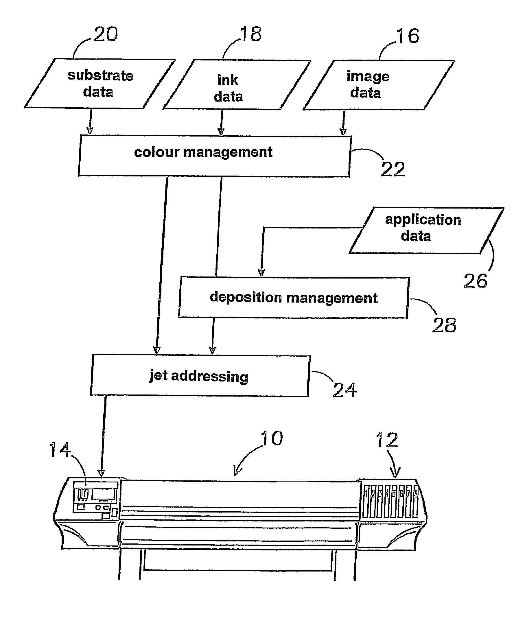
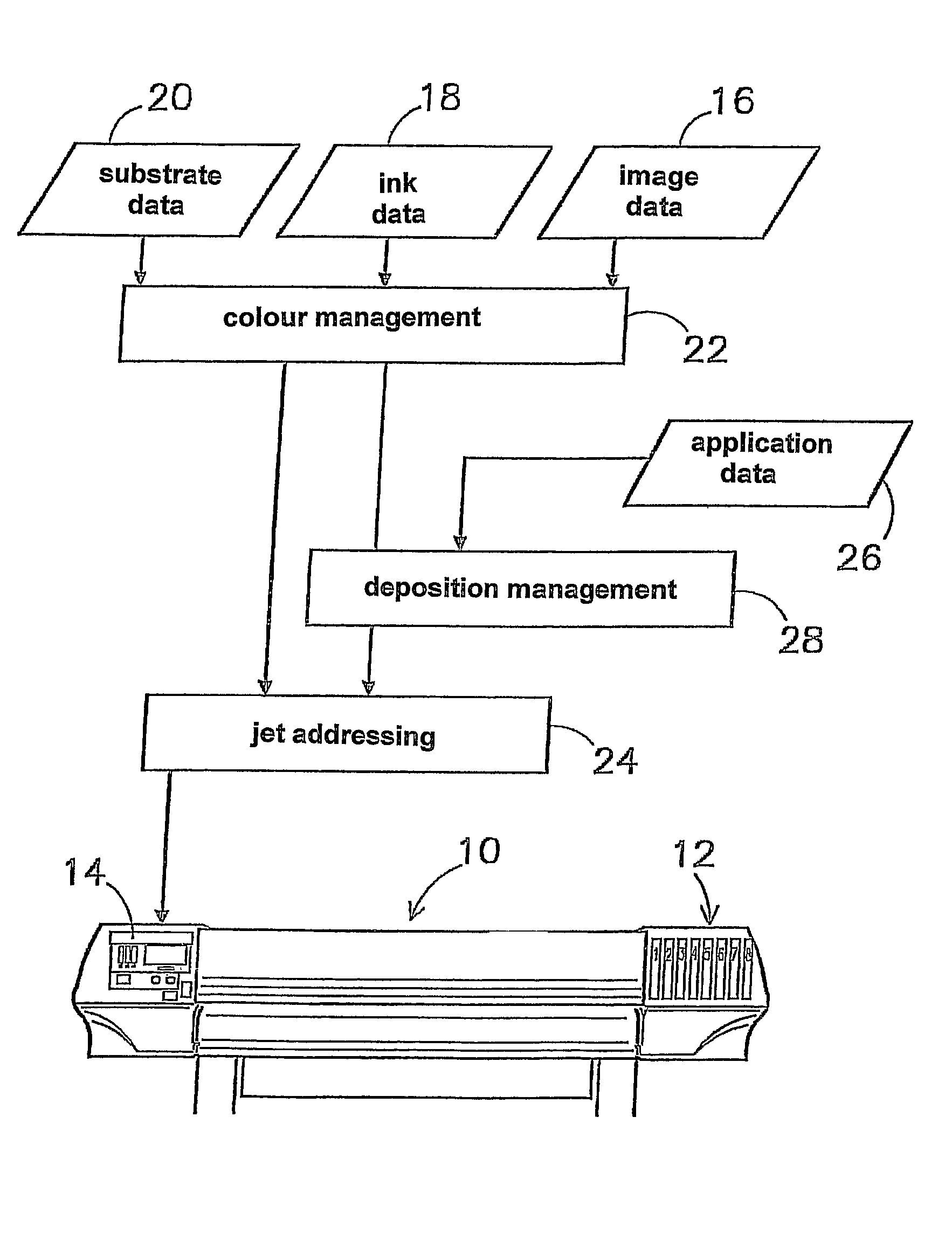
[0065]FIG. 1 shows a standard type of an inkjet printing device 10, which is suitable for printing on wide substrates. This type comprises eight (numbered 1-8) ducts 12, whereof in this case six (121-3 and 126-8) are connected to containers for ink fluids comprising a dye in a main solvent. A duct 124 is connected to a container for transport fluid and a duct 125 is connected to a container for an auxiliary fluid comprising rheology-modifying agents. The ducts 12 are connected to ink nozzles of a print head, which is located on a carriage which can be moved to and fro in the transverse direction (denoted by a double arrow) to the motional direction of the substrate. On the left-hand side, the control device 14 is provided. The control system is explained with reference to the process diagram integrated in this FIGURE. Into the control device 14, the data 16 of the image to be printed, for example as a bit file of the pixel colour values, the data 18 of the used ink fluids and the da...


PUM

PropertyMeasurementUnit
contact angleaaaaaaaaaa

Abstract

In a method for printing on a substrate, in particular a textile substrate, with the aid of an inkjet printing device, a print image to be printed is constructed by drop-by-drop deposition of one or more ink fluids in picture elements which together form the print image, an ink fluid comprising at least one predetermined concentration of at least one dye in a main solvent. The method includes for this purpose the following steps: (a) the determination of the color value of a picture element from the print image, (b) the determination of one or more dye-comprising ink fluids, in dependence on the determined color value, (c) the determination of colorless transport fluid to be applied to the picture element, in dependence on the determined color value, (d) the determination of a colorless auxiliary fluid, comprising rheology-modifying agents, in dependence on the determined color value, and (e) the application of the ink fluids, the transport fluid and the auxiliary fluid to the picture element.

Description

CROSS-REFERENCE TO RELATED APPLICATIONS[0001]This application is the National Stage of International Application No. PCT / NL2007 / 000184, filed Jul. 18, 2007, which claims the benefit of Netherlands Application No. 1032217, filed Jul. 20, 2006, the contents of which is incorporated by reference herein.FIELD OF THE INVENTION[0002]The present invention relates according to a first aspect to a method for printing on a substrate, in particular a textile substrate, with the aid of an inkjet printing device, wherein a print image to be printed is constructed by drop-by-drop deposition of one or more ink fluids in a picture element, an ink fluid comprising at least one predetermined concentration of at least one dye in a main solvent.BACKGROUND OF THE INVENTION[0003]A method for printing on paper is known, for example, from US patent publication US 2005 / 0062819. In this known method, an ink fluid, which contains at least one water-soluble dye and a dispersion of resineous microparticles, is ...

Claims


Application Information

Patent Timeline
Patent Type & Authority Patents(United States)
IPC IPC(8): B41J2/195
CPCB41J2/2114B41J3/4078D06P5/30
Inventor DIEDEREN, JACOBUS HENRICUSPETERS, THEODORUS HENRICUS GERARDUS MARIA
Owner STORK DIGITAL IMAGING BV
Learn More