
Apparatus and methods of compensating for organ deformation, registration of internal structures to images, and applications of same

a technology of organ deformation and apparatus, applied in the field of apparatus and methods of compensating for organ deformation, can solve the problems of increasing the incidence of hepatic resection for colorectal cancer metastasis, uneconomical scaling to mid-level medical centers, and inability to meet the needs of patients,

Active Publication Date: 2013-01-22
VANDERBILT UNIV
View PDF8 Cites 195 Cited by
  • Summary
  • Abstract
  • Description
  • Claims
  • Application Information

AI Technical Summary

Benefits of technology

The present invention provides a way to compensate for shifting of a person's organs during surgery. It is affordable, easy to use in medical facilities, and can adjust to the needs of different patients. This invention also improves the accuracy of surface registration, which helps doctors to align patient's bones and organs accurately. Additionally, it helps to make adjustments when only a portion of the surface is visible. Overall, this invention makes surgery safer and more effective for patients.

Problems solved by technology

While intraoperative magnetic resonance (iMR) and computed tomography (iCT) are available, these approaches are somewhat cumbersome and are not economically scalable to mid-level medical centers.
On the other hand, hepatic tumors represent a major health care problem in the U.S. Along with hepatocellular cancer, many primary neoplasms metastasize to the liver.
This is a frequent problem and the incidence of hepatic resection for colorectal cancer metastasis is increasing [6, 7].
Liver metastases occur in many patients with other primary malignancies (e.g. breast cancer) and are a frequent cause of cancer-related deaths.
Unfortunately, it is estimated that there are only 6,000 to 12,000 patients who would be deemed resectable using current techniques [9].
First, traction on the specimen during division of the liver parenchyma can produce a fracture at the interface of the soft liver tissue and the hard colorectal metastasis.
Second, lack of vascular control during a wedge resection can cause bleeding at the base of the wedge resection.
This bleeding may obscure the transection and compromise the final margin [14].
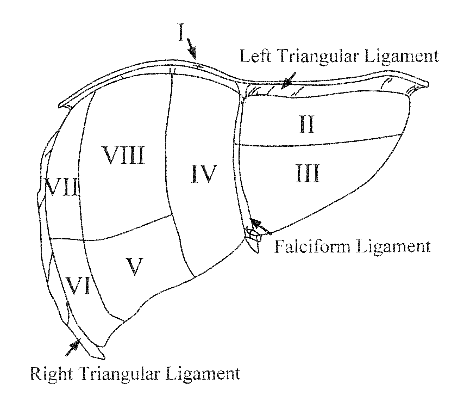
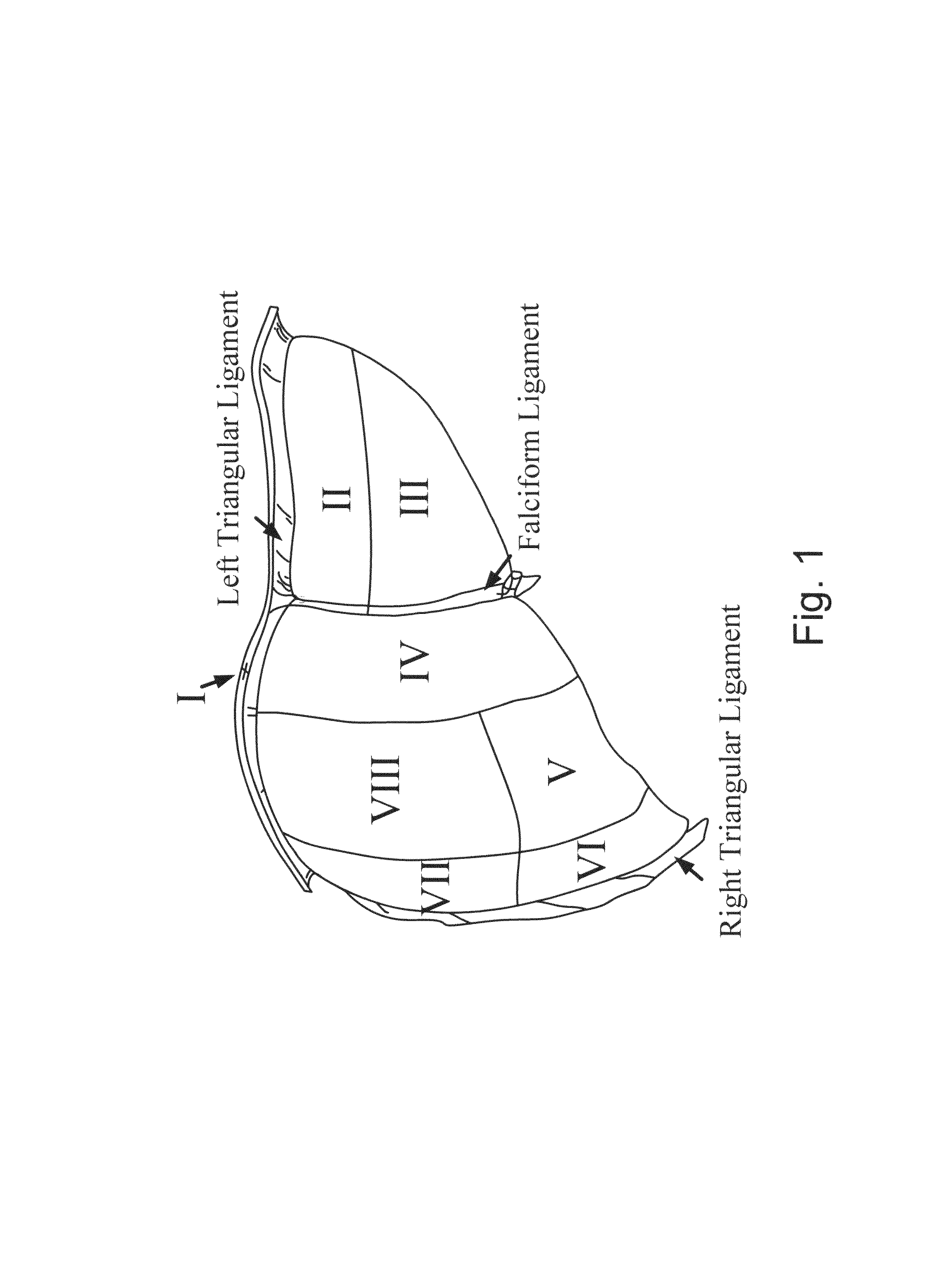
As more liver is removed in a multi-segment or lobectomy procedure, however, there are complications.
It was suspected that as more major liver resections were being conducted, removal of more significant amounts of liver tissue could cause complications.
The paradigm that at least one third of healthy liver volume should be left to avoid hepatic failure following resection has been a standard for many years, but until recently, data did not exist to support this claim.
Being that the surface alignment provided by the ICP algorithm is highly dependent on the initial pose of the surfaces, gross errors in the initial alignment provided by the point-based registration can result in erroneous surface alignments.
A failed surface-based registration not only compromises the guidance information relayed to the surgeon but also impairs deformation correction efforts due to inaccurate surface displacement data that are used to drive mathematical models.
In IGLS, the quality of the initial alignment registration can be compromised by the large fiducial localization errors (FLE) inherent in using anatomical landmarks that undergo non-rigid deformation relative to the preoperative images.
Additionally, gravity and the effects of the liver mobilization and packing performed prior to open liver resections can lead to liver deformations that compromise the results of a rigid ICP surface registration.
Clinical data shows a poor initial alignment registration, due to high FLE of the anatomical fiducials, and large liver deformations resulted in the convergence of the rigid ICP algorithm to a gross misalignment.
Therefore, a heretofore unaddressed need exists in the art to address the aforementioned deficiencies and inadequacies.

Method used


Image

  • Apparatus and methods of compensating for organ deformation, registration of internal structures to images, and applications of same
  • Apparatus and methods of compensating for organ deformation, registration of internal structures to images, and applications of same
  • Apparatus and methods of compensating for organ deformation, registration of internal structures to images, and applications of same

Examples


example 1

Compensation for Intraoperative Organ Shift

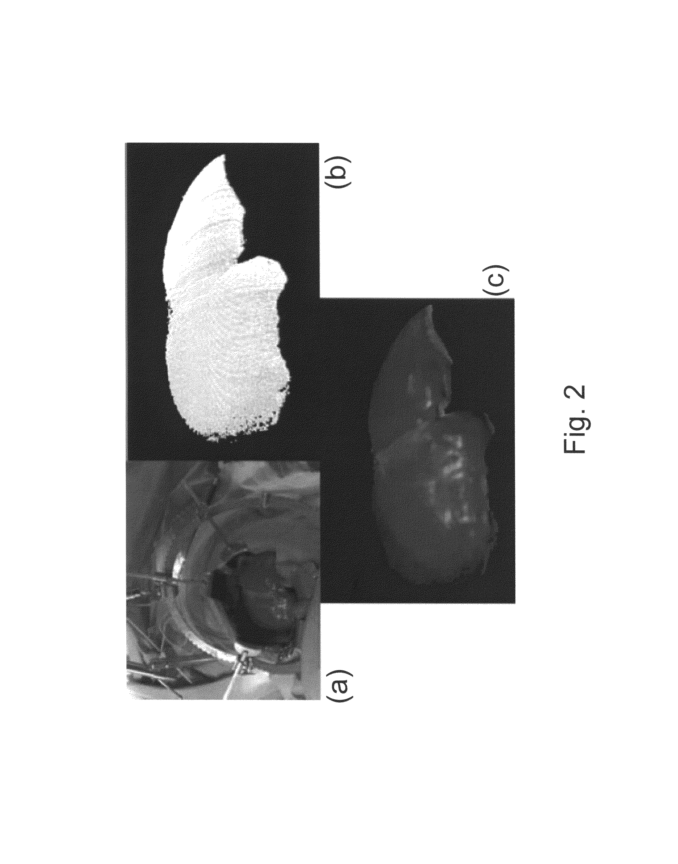
[0186]A. Image-Guided Liver Surgery System: The current image-guided liver surgery (IGLS) system is developed through collaborative efforts between researchers at Vanderbilt University, Washington University in St. Louis, and Pathfinder Therapeutics Inc. (PTI), and has been used to collect data in more than 15 clinical cases. This working prototype has been in development for over eight years. Preoperative CT and MR images are acquired from the liver of a patient one to two weeks before the procedure. The liver of the patient is segmented from these preoperatively acquired image volumes. This segmentation can be performed by manually outlining the contour of the liver surface. However, the manual procedure is often very slow and tedious and may require hours to complete. An alternative and more expedient semi-automatic method was developed by Dr. Benoit Dawant at Vanderbilt University which is based on the level-set technique [30, 31]. This...

example 2

Compensating for Intraoperative Soft-Tissue Deformations Using Incomplete Surface Data and Finite Elements

[0214]The IGLS requires the ability to identify and compensate for soft tissue deformation in the organ. The predeformed state is represented as a complete three-dimensional surface of the organ, while the intraoperative data is a range scan point cloud acquired from the exposed liver surface. The first step is to rigidly align the coordinate systems of the intraoperative and preoperative data. Most traditional rigid registration methods minimize an error metric over the entire data set. In this Example, a new deformation-identifying rigid registration (DIRR) is reported that identifies and aligns minimally deformed regions of the data using a modified closest point distance cost function. Once a rigid alignment has been established, deformation is accounted for using a linearly elastic finite element model (FEM) and implemented using an incremental framework to resolve geometri...

example 3

Robust Surface Registration Using Salient Anatomical Features—a Patch Approach

[0268]This example relates to how to implement a surface based registration method that utilizes the homologous, salient anatomical features to ensure convergence to reasonable solutions under conditions of poor initial alignment. Additionally, the robustness and feasibility of the implemented algorithm are demonstrated, relative to the traditional ICP based method, using both phantom and clinical data.

Method

[0269]A. Overview: The implemented weighted patch ICP algorithm in this embodiment is effectively a novel, non-obvious extension of the WGF algorithm proposed by Maurer et al. The homologous anatomical features, or patches, will be used to both bias point correspondence determination as well as play a more significant role in the PBR performed at each iteration of the algorithm. The weighting scheme used to bias the PBR is dynamic over the course of the algorithm where the homologous patch regions play...


PUM


Abstract

A method and system of compensation for intra-operative organ shift of a living subject usable in image guide surgery. In one embodiment, the method includes the steps of generating a first geometric surface of the organ of the living subject from intra-operatively acquired images of the organ of the living subject, constructing an atlas of organ deformations of the living subject from pre-operatively acquired organ images from the pre-operatively acquired organ images, generating a second geometric surface of the organ from the atlas of organ deformations, aligning the second geometric surface of the organ to the first geometric surface of the organ of the living subject to determine at least one difference between a point of the first geometric surface and a corresponding point of the second geometric surface of the organ of the living subject, which is related to organ shift, and compensating for the intra-operative organ shift.

Description

CROSS-REFERENCE TO RELATED PATENT APPLICATION[0001]This application claims the benefit, pursuant to 35 U.S.C. §119(e), of U.S. provisional patent application Ser. No. 60 / 859,438, filed Nov. 16, 2006, entitled “APPARATUS AND METHODS FOR COMPENSATING FOR ORGAN DEFORMATION, APPARATUS AND METHODS FOR REGISTRATION OF INTERNAL STRUCTURES TO IMAGES, AND APPLICATIONS OF SAME,” by Michael I. Miga, Logan Clements and Robert L. Galloway Jr., which is incorporated herein by reference in its entirety.[0002]Some references, which may include patents, patent applications and various publications, are cited and discussed in the description of this invention. The citation and / or discussion of such references is provided merely to clarify the description of the present invention and is not an admission that any such reference is “prior art” to the invention described herein. All references cited and discussed in this specification are incorporated herein by reference in their entireties and to the sa...

Claims


Application Information

Patent Timeline
Patent Type & Authority Patents(United States)
IPC IPC(8): G06K9/00
CPCA61B19/52G06T7/0032A61B2017/00694A61B2019/5289A61B6/583G06T2207/10028G06T2207/10072G06T2207/30056A61B90/36A61B2090/364G06T7/344
Inventor MIGA, MICHAEL I.CLEMENTS, LOGAN W.GALLOWAY, JR., ROBERT L
Owner VANDERBILT UNIV
Learn More