
Making storage system having modifiable conductor and memory

a technology of conductor and memory, applied in the field of storage systems, can solve the problems of inability to determine the success of such an update when away from the reader, the cost of the intended tracking purpose is typically high, and the rfid reader is generally short-range, so as to reduce the cost and space requirements, improve security and reliability, and reduce the cost of equipmen

Inactive Publication Date: 2013-01-22
EASTMAN KODAK CO
View PDF13 Cites 7 Cited by
  • Summary
  • Abstract
  • Description
  • Claims
  • Application Information

AI Technical Summary

Benefits of technology

The present invention provides a unique identifier for a product or container without the need for a unique transceiver integrated circuit. This allows for the use of lower-cost equipment and larger substrates, reducing space requirements and cost. The unique identification codes have improved security and reliability due to their ability to change electrical characteristics. The invention also provides a simplified process flow compared to conventional systems using laser-trimmed RFID ICs and is resistant to hostile environments. Additionally, the invention allows for visible or tamper-evident recording of data, as well as an automatically-maintained history of data changes. This permits updating a status record of the container without a reader and maintaining the advantage of traceability provided by a memory.

Problems solved by technology

The transponder circuits are typically constructed from integrated circuits and can be expensive for the intended tracking purpose.
Moreover, the success of such an update cannot be determined when away from a reader.
Furthermore, RFID readers are generally short-range, so it is difficult to use one reader for communications with widely-scattered RFID tags, e.g., in a large warehouse.
It is also problematic to associate RFID tags to specific containers, for example by affixing the tag to the container, without error or confusion.
Moreover, affixed tags can be removed and lose their effectiveness at reducing errors or theft.

Method used


Image

  • Making storage system having modifiable conductor and memory
  • Making storage system having modifiable conductor and memory
  • Making storage system having modifiable conductor and memory

Examples


Embodiment Construction

[0056]In the following description, some embodiments will be described in terms that would ordinarily be implemented as software programs. Those skilled in the art will readily recognize that the equivalent of such software can also be constructed in hardware. Because communications algorithms and systems are well known, the present description will be directed in particular to algorithms and systems forming part of, or cooperating more directly with, systems and methods described herein. Other aspects of such algorithms and systems, and hardware or software for producing and otherwise processing the data involved therewith, not specifically shown or described herein, are selected from such systems, algorithms, components, and elements known in the art. Given the systems and methods as described herein, software not specifically shown, suggested, or described herein that is useful for implementation of any embodiment is conventional and within the ordinary skill in such arts.

[0057]F...


PUM


Abstract

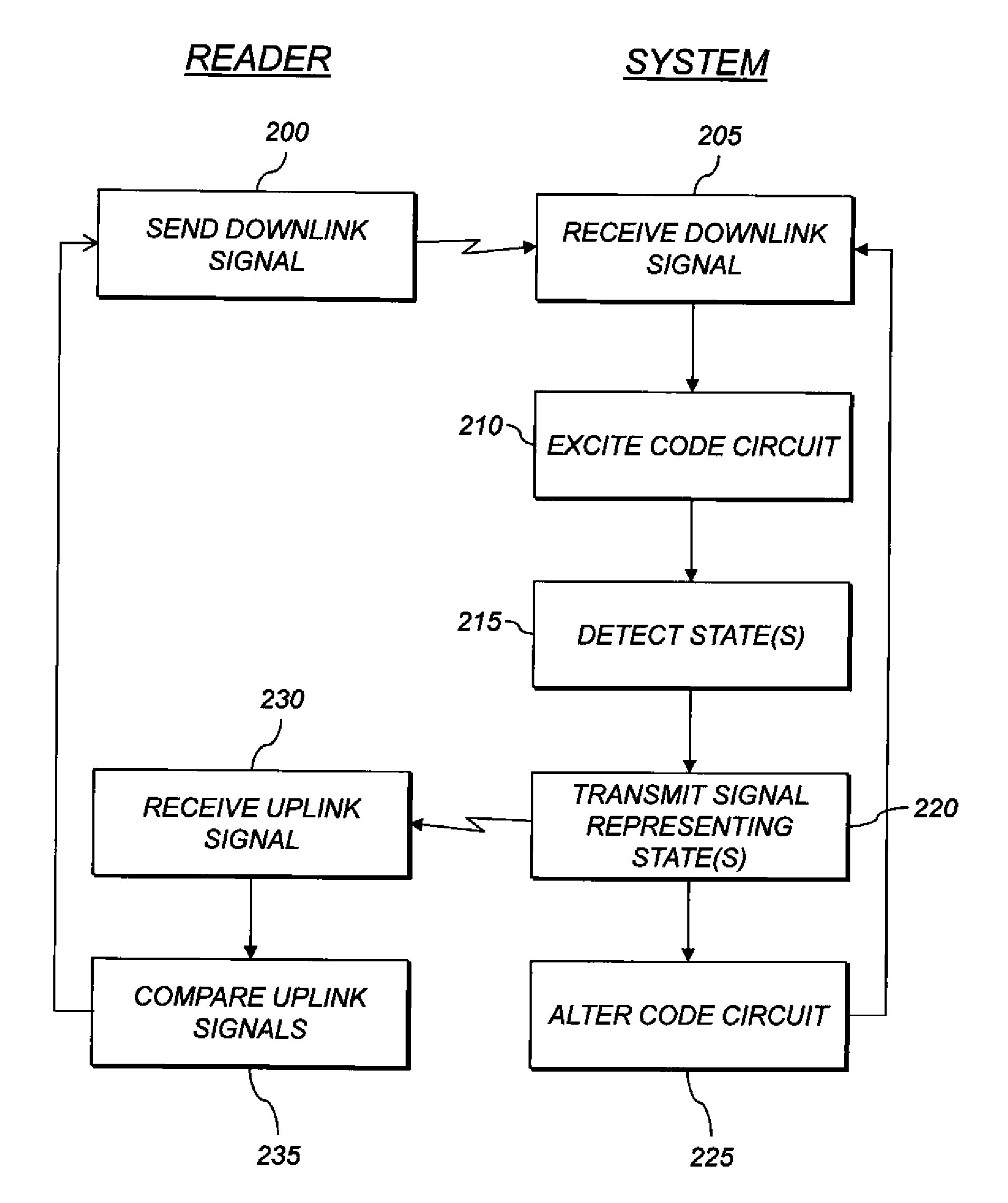
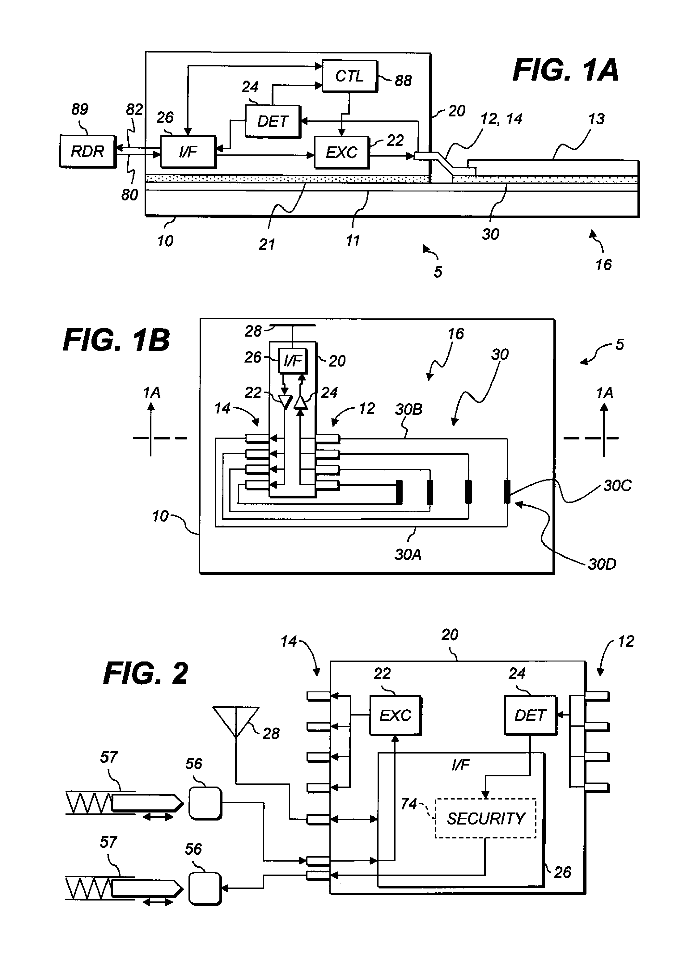
An electronic storage system includes a substrate with a state region, a transceiver with memory and a controller, and a code circuit disposed over the substrate separate from the transceiver and electrically connected thereto. The code circuit includes a conductor whose electrical or mechanical state can be externally altered. At intervals, the transceiver electrically excites the code circuit and detects the electrical state of an input pad connected to the code circuit. The electrical state corresponds to the excitation and to the electrical or mechanical state of the conductor. The controller stores the detected state or a representation thereof in the memory. In response to a downlink signal, the transceiver transmits an uplink signal representing the stored detected electrical state(s) of the input pad, or the stored representations thereof.

Description

CROSS REFERENCE TO RELATED APPLICATIONS[0001]Reference is made to commonly assigned U.S. application Ser. No. 13 / 455,167, filed Apr. 25, 2012, titled “ELECTRONIC STORAGE SYSTEM WITH CODE CIRCUIT;” U.S. application Ser. No. 13 / 455,377, filed Apr. 25, 2012, titled “MAKING ELECTRONIC STORAGE SYSTEM HAVING CODE CIRCUIT;” U.S. application Ser. No. 13 / 455,257, filed Apr. 25, 2012, titled “ELECTRONIC STORAGE SYSTEM WITH EXTERNALLY-ALTERABLE CONDUCTOR;” U.S. application Ser. No. 13 / 455,367, filed Apr. 25, 2012, titled “ALTERING CONDUCTOR IN ELECTRONIC STORAGE SYSTEM;” U.S. application Ser. No. 13 / 455,360, filed Apr. 25, 2012, titled “ELECTRONIC STORAGE SYSTEM WITH ENVIRONMENTALLY-ALTERABLE CONDUCTOR;” and U.S. application Ser. No. 13 / 455,390, filed Apr. 25, 2012, titled “MAKING STORAGE SYSTEM HAVING ENVIRONMENTALLY-MODIFIABLE CONDUCTOR;” the disclosures of which are incorporated by reference herein in their entirety.FIELD OF THE INVENTION[0002]The present invention relates to storing data, ...

Claims


Application Information

Patent Timeline
Patent Type & Authority Patents(United States)
IPC IPC(8): G06K19/06
CPCG06K19/0717
Inventor COK, RONALD STEVENLYONS, CHRISTOPHER
Owner EASTMAN KODAK CO
Learn More