Optical analyte sensor

an analyte sensor and optical technology, applied in the field of analyte detection, can solve the problems of reducing the applicability of local detection characteristics of atr and rsw waveguide analyte sensors to complex and multiple analyte environments, requiring complex sample preparation, and limited number of conventional atr and rsw waveguide analyte sensors

Active Publication Date: 2013-01-08
COLORADO STATE UNIVERSITY
View PDF8 Cites 19 Cited by
  • Summary
  • Abstract
  • Description
  • Claims
  • Application Information

AI Technical Summary

Benefits of technology

The present invention is about a sensor that can detect multiple substances at the same time without needing to be labeled with fluorescent markers. This is possible because the sensor has a thin core region that creates a large evanescent field, which is able to interact with multiple adlayer regions. This allows for the simultaneous detection of multiple antigens or pathogens, making it useful for a variety of medical, security, and environmental applications.

Problems solved by technology

Conventional ATR and RSW waveguide analyte sensors are often limited in the number of analytes that can be simultaneously detected by one sensor, and require complex sample preparation; that is, the large size and non-local detection characteristic of these sensors diminishes their applicability to complex and multiple analyte environments.
Additionally, sensors using florescence spectrometry require that the target samples be prepared with chemically specific dyes or labels which increases the complexity and overall cost for analyses.

Method used


Image

  • Optical analyte sensor
  • Optical analyte sensor
  • Optical analyte sensor

Examples


Embodiment Construction

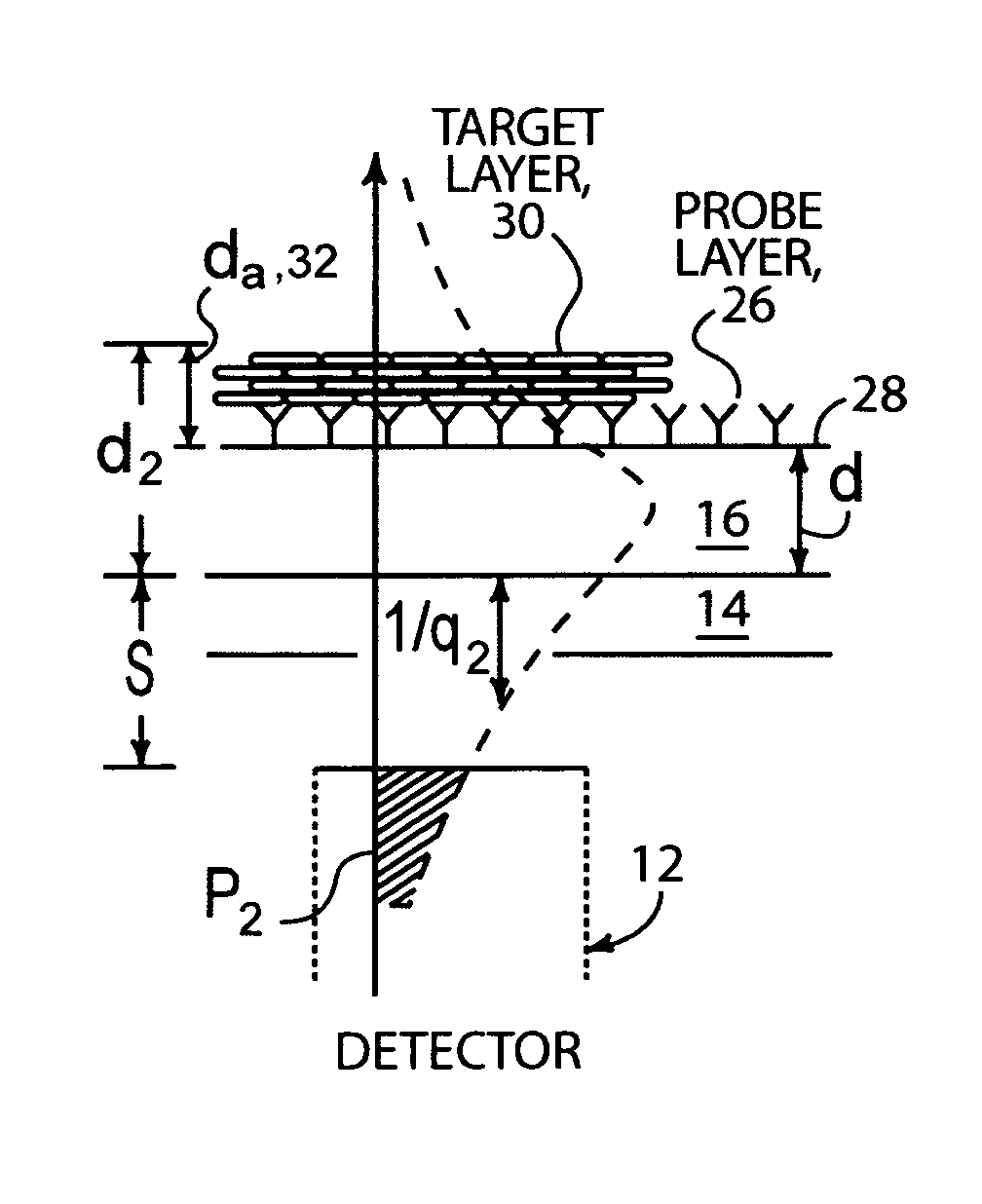
[0029]Briefly, the present invention includes a waveguide sensor that for simultaneously detecting multiple analytes. The process of detection does not require labeling of the analytes with fluorescent or other tags. The waveguide has a thin core that can create large evanescent fields which can be detected in the region of the evanescent field and which fields interact with adlayer regions through which the evanescent fields pass, thereby generating changes in the field intensity.

[0030]In another embodiment of the invention, light may be coupled out of the waveguide in amounts which vary as a result of the interaction of the core with the analyte.

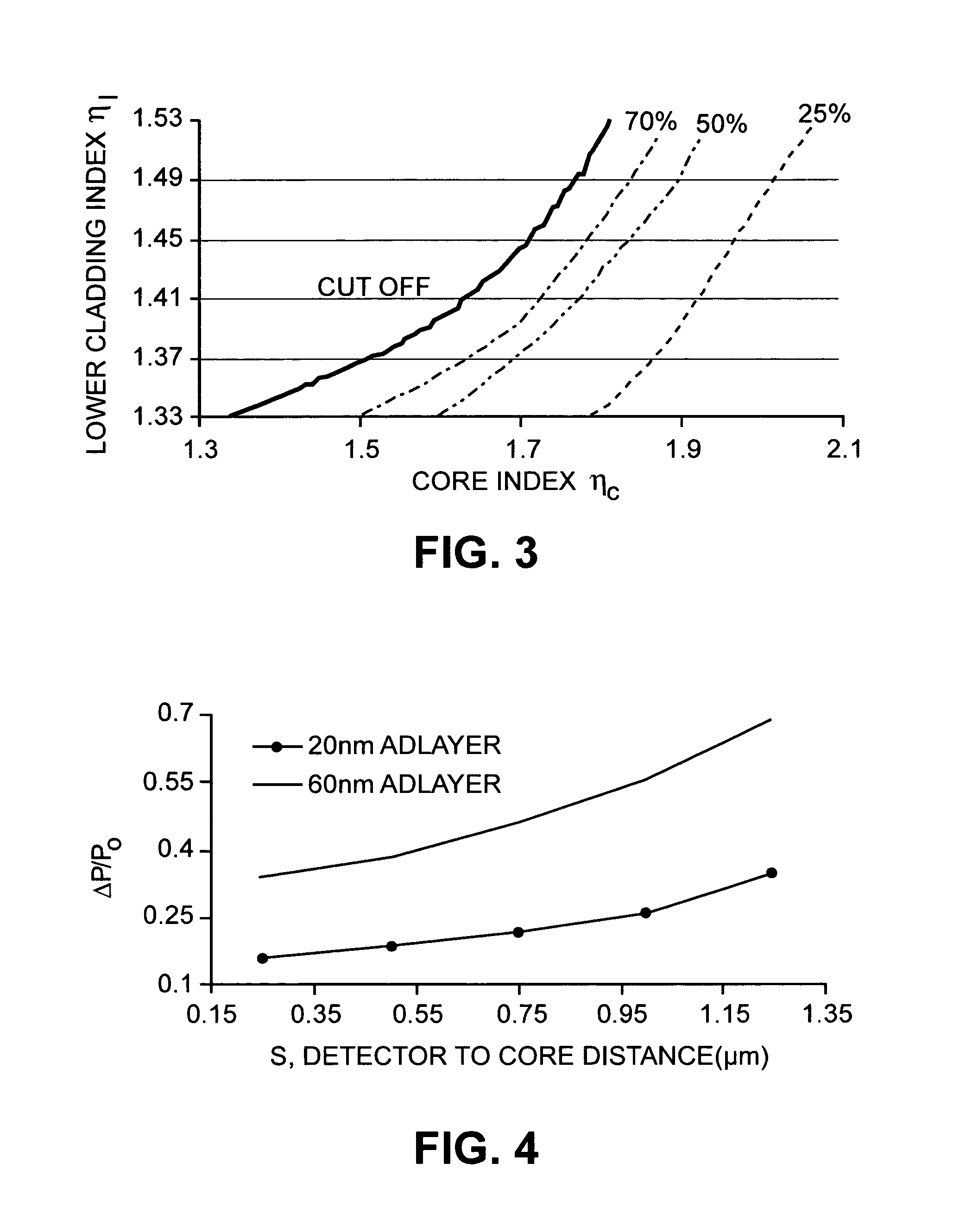
[0031]It has been theoretically determined by the present inventors that the power distribution of the electromagnetic field in the waveguide is dependent on the thickness of adlayers which are assumed, in the calculations which follow, to be target species bound to patches of probe species immobilized in the vicinity of the waveguide surf...


PUM

PropertyMeasurementUnit
widthaaaaaaaaaa
refractive indexaaaaaaaaaa

Abstract

A waveguide sensor capable of direct, real-time detection and monitoring of analytes in the vicinity of the waveguide surface without requiring the tagging or labeling of the analyte, is described. Analytic and numerical calculations have predicted that by locally detecting either changes in the evanescent field or changes in the light coupled out of the waveguide as a result of the presence of the analyte, high detection sensitivity will be able to be achieved.

Description

RELATED CASES[0001]The present application claims the benefit of provisional patent application Ser. No. 60 / 670,939 for “Multi-Analyte Optical Sensor” by Kevin L. Lear et al., filed on Apr. 12, 2005, which application is hereby incorporated by reference herein for all that it discloses and teaches.STATEMENT REGARDING FEDERAL RIGHTS[0002]This invention was made with government support under Grant No. EB 00726 awarded by the U.S. National Institutes of Health to Colorado State University. The government has certain rights in the invention.FIELD OF THE INVENTION[0003]The present invention relates generally to analyte detection and, more particularly, to the use of evanescent and coupled electromagnetic waves from optical waveguide structures for sensing analytes.BACKGROUND OF THE INVENTION[0004]The low absorption loss, high sensitivity, and flexible light detection abilities of integrated optical waveguide analyte sensors make them suitable for many practical biological and chemical en...

Claims


Application Information

Patent Timeline
Patent Type & Authority Patents(United States)
IPC IPC(8): C12M1/34
CPCG01N21/552G01N21/7703G01N33/54373G01N21/41G01N2201/06113G01N2201/062G01N2201/08
Inventor LEAR, KEVIN L.DANDY, DAVID S.STEPHENS, MATTHEW D.YUAN, GUANGWEI
Owner COLORADO STATE UNIVERSITY
Why Eureka
Try Eureka