
Electric precipitator and electrode thereof

a precipitator and electrode technology, applied in the direction of electrostatic separation, solid separation, chemistry apparatus and processes, etc., can solve the problems of dielectric breakdown or discharge between the electrodes, increased output, and increased current leaked through the spacer or the protrusion, so as to prevent dielectric breakdown

Active Publication Date: 2013-01-08
SAMSUNG ELECTRONICS CO LTD
View PDF14 Cites 17 Cited by
  • Summary
  • Abstract
  • Description
  • Claims
  • Application Information

AI Technical Summary

Benefits of technology

[0011]Accordingly, it is an aspect of the disclosure to prevent dielectric breakdown by ensuring the dielectric distance among a plurality of electrodes.
[0012]It is another aspect of the disclosure to prevent space electric field strength from being reduced by separately providing a conductive protrusion and a dielectric protrusion which maintain a gap among a plurality of electrodes.
[0026]Further, the first part is manufactured in a form of slurry including first conductive materials, a binder for improving bonding force of the first conductive materials, and second conductive material for preventing conductivity from being reduced due to the binder.
[0027]Further, the second part is manufactured in a form of slurry including dielectric materials and a binder for improving bonding force of the dielectric materials.

Problems solved by technology

However, if dust is accumulated on a surface of an electrode, electric current is instantaneously applied to the accumulated dust from a conductive electrode, so dielectric breakdown or discharge may occur between the electrodes.
Further, if resistivity of the plastic resin found in the high and low voltage electrodes is reduced to solve such problems, electric current leaked through the spacer or the protrusion is increased.
Thus, power supply output is increased, so power loss may occur.

Method used


Image

  • Electric precipitator and electrode thereof
  • Electric precipitator and electrode thereof
  • Electric precipitator and electrode thereof

Examples


Embodiment Construction

[0038]Hereinafter, exemplary embodiments of the disclosure will be described in detail with reference to accompanying drawings.

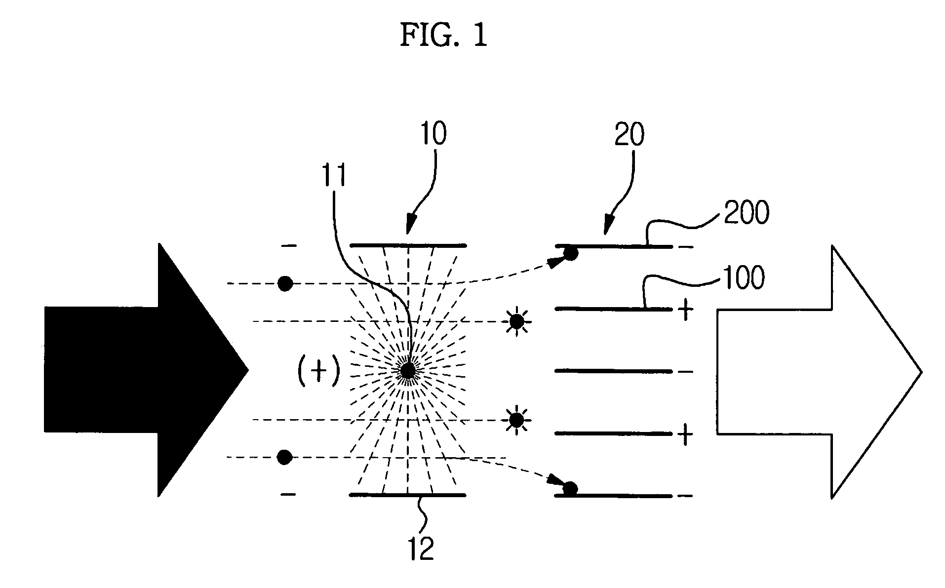
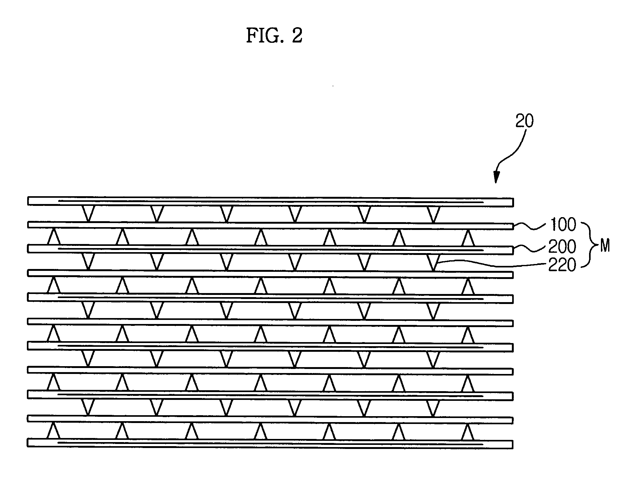
[0039]FIG. 1 is a view illustrating a basic principle of a two-stage electric precipitator according to an embodiment and FIG. 2 is a sectional view illustrating a collection section of the two-stage electric precipitator according to the embodiment.

[0040]As illustrated in FIGS. 1 and 2, the electric precipitator according to the embodiment includes a charging section 10 that electrolyzes dust in the air, and a collecting section 20 that collects dust particles charged by the charging section 10.

[0041]The charging section 10 includes a discharge line 11 having a thin wire shape made of tungsten material and serving as an anode, and a pair of opposite discharge plates 12 which are longitudinally arranged while being spaced apart from the discharge line 11 and serving as a cathode.

[0042]As high voltage is applied to the discharge line 11, electric current star...


PUM

PropertyMeasurementUnit
voltageaaaaaaaaaa
areaaaaaaaaaaa
conductivityaaaaaaaaaa

Abstract

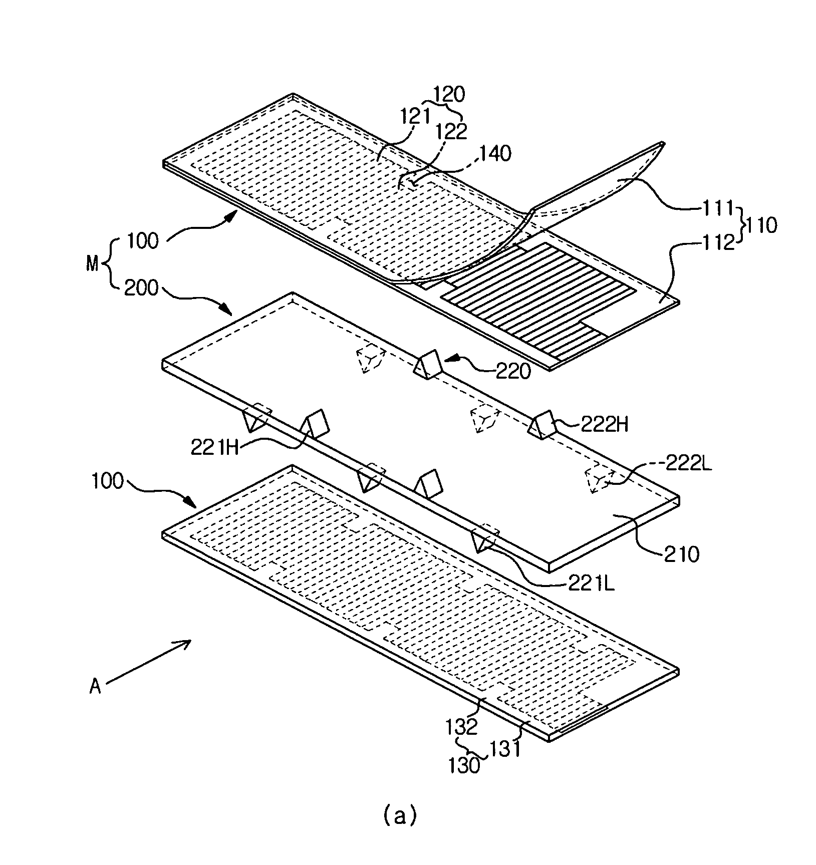
An electric precipitator prevents dielectric breakdown by ensuring the dielectric distance among a plurality of electrodes. The electric precipitator includes a charging section for charging dust particles in air, and a collecting section for collecting the dust particles charged by the charging section. The collecting section includes a high voltage electrode having a conductive layer coated with a dielectric layer, and a low voltage electrode having at least one protrusion that maintains a gap between the high voltage electrode and the low voltage electrode. The conductive layer includes at least one cutting part formed in an area corresponding to the protrusion.

Description

CROSS-REFERENCE TO RELATED APPLICATIONS[0001]This application claims the benefit of Korean Patent Application No. 10-2008-0120557, filed on Dec. 1, 2008, in the Korean Intellectual Property Office, the disclosure of which is incorporated herein by reference.BACKGROUND[0002]1. Field[0003]The disclosure relates to an electric precipitator. More particularly, the disclosure relates to an electric precipitator capable of preventing dielectric breakdown by ensuring the dielectric distance among a plurality of electrodes.[0004]2. Description of the Related Art[0005]In general, an electric precipitator is installed in an air conditioning system to purify the air by collecting and removing contaminant such as dust contained in the air.[0006]The electric precipitator mainly employs a two-stage electric precipitation scheme by separately providing a charging section and a collecting section. The collecting section forms an electric field by arranging a high voltage electrode and a low voltage...

Claims


Application Information

Patent Timeline
Patent Type & Authority Patents(United States)
IPC IPC(8): B03C3/12B03C3/47
CPCB03C3/08B03C3/47Y10T29/49002B03C2201/10B03C2201/04
Inventor NOH, HYONG SOOYASUHIKO, KOCHIYAMAJI, JUN HOYUN, SO YOUNGCHO, HAN WOOK
Owner SAMSUNG ELECTRONICS CO LTD
Learn More