
Method for recognizing objects in images

a technology for objects and images, applied in the field of methods for recognizing objects in images, can solve the problems of difficulty in distinguishing actual image color variations from color variations, requiring a series of complex computations, and not using prior information concerning known image color content in segmentation methods

Inactive Publication Date: 2012-12-25
NAT TAIWAN UNIV
View PDF15 Cites 21 Cited by
  • Summary
  • Abstract
  • Description
  • Claims
  • Application Information

AI Technical Summary

Benefits of technology

The present invention provides a method for quickly identifying and locating objects in an image using a combination of histogram analysis and polynomial regression analysis. The method can be used in various fields such as traffic signs and can be implemented using a computer program. The technical effects of the invention include improved efficiency and accuracy in identifying and locating objects in images.

Problems solved by technology

However, the segmentation method does not make use of prior information concerning known image color content and the color histograms which are created do not maintain geometry information.
As a result, the method still requires a series of complex computations to complete the object recognition process.
However, in practice, actual image color variations may be difficult to distinguish from color variations that result from either noise or the nonlinear transformation from RGB to IHS color space.
In addition, the method still requires a significant amount of processing time for creating model histograms and comparing input image histograms to model histograms.
The color histogram generation technique used does not preserve geometry, just an accounting of the number of image pixels of given colors.
As a result, actual object shape, size, and location cannot be determined.
Finally, similar histograms for different objects may lead to inaccurate object recognition results.
However, creating a model image database for histogram matching takes a significant amount of time.
Computing co-occurrence histograms by computing distance measures for every possible unique, non-ordered pair of pixels in both the model images and the search image is also computationally expensive.
The resulting object location determination is not precise, and subsequent iterative refinement of the determined location is computationally intensive.
Further, method parameters, such as search window size, affect object recognition accuracy, and images must be scaled to handle overall size differences between search and model images.
In general, correlation-based classifiers can be imprecise and / or slow.
In turn, a large stored database requires more processing time to complete correlations.
As an example, circular and square objects appear as varying oval and rectangular shapes from different viewing angles, which could reduce object recognition accuracy.
However, direct image searching methods and, in particular, edge detection and pixel-by-pixel pattern matching methods are generally imprecise and relatively slow.
In addition, both sign and sign symbol shape and size vary significantly, based upon vehicle position with respect to a given traffic sign, which further hinders accurate shape matching and object recognition using edge detection and pixel-by-pixel matching.
The disadvantage of the method is the fact that the shape and size of an object can not be correctly calculated if there is a misalignment between an image capture device and the object.

Method used


Image

  • Method for recognizing objects in images
  • Method for recognizing objects in images
  • Method for recognizing objects in images

Examples


first embodiment

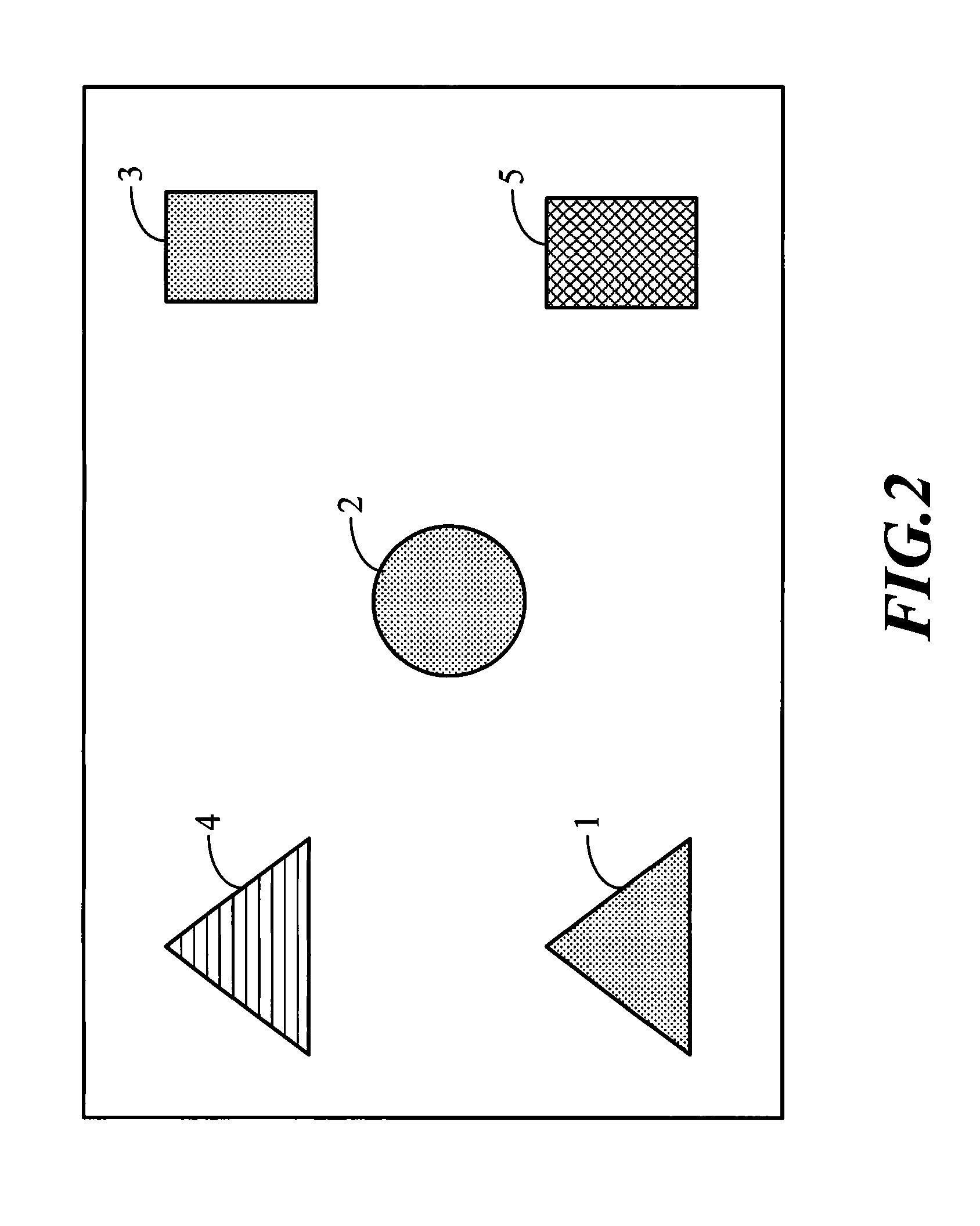
[0124]FIG. 2 is an image containing five objects in the present invention.

[0125]FIG. 3 is a segmented image of FIG. 2 (only the red objects are kept).

[0126]FIG. 4 is an x-axis histogram for FIG. 3 by counting the number of red pixels in each column in the x-axis of FIG. 3.

[0127]FIG. 5 is a y-axis histogram for FIG. 3 by counting the number of red pixels in each row in the y-axis of FIG. 3.

second embodiment

[0128]FIG. 6 is a color image containing several objects for the present invention.

[0129]FIG. 7 is a segmented image of FIG. 6 (containing only the red objects).

[0130]FIG. 8 is an x-axis histogram for FIG. 6 by counting the number of red pixels in each column along the x-axis of FIG. 6.

[0131]FIG. 9 is a y-axis histogram for FIG. 6 by counting the number of red pixels in each row along the y-axis of FIG. 6.

[0132]

List of reference numerals   1 Red triangle   2 Red circle   3 Red rectangle   4 Green triangle   5 Blue rectangle   6 Traffic sign  61 Red outer ring  62 White inside  63 Black number  71 Red flowers 101 Triangular figure1011 Curve / straight line1012 Curve / straight line 102 Triangular figure 201 Curved figure2011 Curve 202 Curved figure 301 Rectangular figure3011 Curve / line3012 Curve / line3013 Curve / line 302 Rectangular figure 501 Centrally concave pattern5011 Curve5012 Curve5013 Curve5014 Curve 502 Red flower pattern 503 Red blossom patternA, C, D, F, G and J ZeroesB, E, H an...


PUM


Abstract

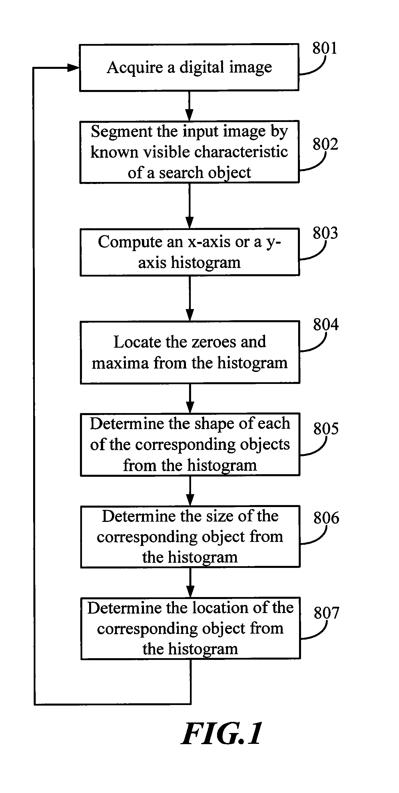
A method for recognizing objects in images is disclosed. The method of the present invention comprises the following steps. First, acquire a digital image. Then, select one or more objects from the image according to a certain characteristic. Next, generate an x-axis histogram and / or a y-axis histogram from the segmented image. Then, find the zeroes and maxima for the x-axis histogram and / or the y-axis histogram and use the polynomial regression analysis to determine the shape, shape and location of each of the objects in the segmented image according to the zeroes and maxima. If the two curves linking two zeroes and one maximum in the x-axis histogram and the y-axis histogram are two sloped line, the corresponding object may be determined to be a triangle. If each of the four curves linking two zeroes and two maxima is a line, the corresponding object may be determined to be a rectangle.

Description

BACKGROUND OF THE INVENTION[0001]1. Field of the Invention[0002]The invention generally relates to a method for recognizing objects in images. More particularly, the invention relates to a method by which the shape, size and position of an object may be accurately and swiftly determined.[0003]2. Description of the Prior Art[0004]The object recognition system in the prior art includes the following five steps: (1) Acquire an image by a still camera or a similar device (2) Segment the image (3) Extract objects from the segmented image (4) Abstract the extracted objects (5) Classify the abstract objects.[0005]Captured input images are typically composed of color or gray-scale pixel data in digital format, arranged as two-dimensional matrices in the x (horizontal) and y (vertical) directions. Images may contain thousands or millions of individual pixels.[0006]At the lowest level of abstraction (no abstraction at all), objects can be modeled as whole images and compared, pixel by pixel, ...

Claims


Application Information

Patent Timeline
Patent Type & Authority Patents(United States)
IPC IPC(8): G06K9/00G06K9/34
CPCG06K9/00818G06K9/4647G06V20/582G06V10/507
Inventor SMITH, GREGORY C.SMITH, SHANA S.
Owner NAT TAIWAN UNIV
Learn More