Audio encoding method and device

a technology of which is applied in the field of audio encoding method and encoding device, can solve problems such as affecting the quality of the signal, and achieve the effect of simple and inexpensive perception of the signal and good quality

Active Publication Date: 2012-12-25
NINTENDO EUROPEAN RESEARCH & DEVELOPMENT
View PDF17 Cites 0 Cited by
  • Summary
  • Abstract
  • Description
  • Claims
  • Application Information

AI Technical Summary

Benefits of technology

[0005]This problem is advantageously resolved by the transmission, in addition to the data representing the frequency-limited signal, of information relating to a temporal filter that is to be applied to the whole of the enhanced signal, both in its transmitted low-frequency part and in its reconstituted high-frequency part, the application of this filter allowing the reshaping of the reconstituted high-frequency part and the correction of compression artefacts present in the transmitted low-frequency part. In this way, the application of the temporal filter, which is simple and inexpensive, to the whole of the reconstituted signal makes it possible to obtain a good-quality perceived signal.
[0006]The invention concerns a method of encoding all or part of a multi-channel audio stream comprising a step of obtaining a complex signal obtained by the composition of signals corresponding to each channel of the multi-channel audio stream; a step of obtaining a frequency-limited complex signal, the reduction of the frequency of the original complex signal being obtained by suppression of the high frequencies, and a step of generating one temporal filter per channel making it possible to find a signal spectrally close to the original signal of the corresponding channel when it is applied to the signal obtained by broadening of the spectrum of the limited composite signal.
[0018]According to a particular embodiment of the invention, one of the channels of the multi-channel stream being defined as the reference channel, an offset value being associated with each filter received for the channels other than the reference channel, the method also comprises a step of offsetting the signal corresponding to each channel other than the reference channel making it possible to generate a temporal phase difference similar to the temporal phase difference between each channel and the reference channel in the original multi-channel audio stream.
[0019]According to a particular embodiment of the invention, the method also comprises a step of smoothing the offset values at the boundaries between the working windows so as to avoid an abrupt change in the offset value for each channel other than the reference channel.
[0020]According to a particular embodiment of the invention, one of the channels of the multi-channel stream being defined as the reference channel, an amplification value being associated with each filter received for the channels other than the reference channel, the method also comprises a step of amplifying the signal corresponding to each channel other than the reference channel and making it possible to generate a difference in gain similar to the difference in gain between each channel and the reference channel in the original multi-channel audio stream.
[0021]The invention also concerns a device for encoding a multi-channel audio stream comprising at least means of obtaining a composite signal obtained by composition of the signals corresponding to each channel of the multi-channel audio stream; means of obtaining a frequency-limited composite signal, the reduction of the spectrum of the original composite signal being obtained by suppression of the high frequencies and means of generating one temporal filter per channel, making it possible to find a signal spectrally close to the original signal of the corresponding channel when it is applied to the signal obtained by broadening the spectrum of the limited signal.

Problems solved by technology

It turns out that the compression and method used for compressing and limiting the bandwidth of the initial frequency generate artefacts impairing the quality of the signal.

Method used


Image

  • Audio encoding method and device
  • Audio encoding method and device
  • Audio encoding method and device

Examples


Embodiment Construction

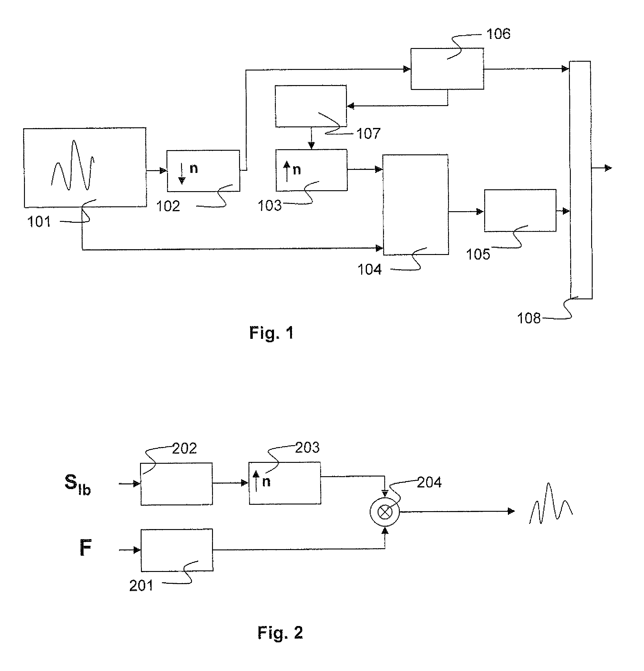
[0030]FIG. 1 shows the encoding method in general terms. The signal 101 is the source signal that is to be encoded, and this signal is then the original signal not limited in terms of frequency. Step 102 shows a step of frequency limitation of the signal 101. This frequency limitation can for example be implemented by a subsampling of the signal 101 previously filtered by a low-pass filter. A subsampling consists of keeping only one sample on a set of samples and suppressing the other samples from the signal. A subsampling by a factor of “n” where one sample out of n is kept makes it possible to obtain a signal where the width of the spectrum will be divided by n. n is here a natural integer. It is also possible to effect a subsampling by a rational ratio q / p; supersampling is carried out by a factor p and then subsampling by a factor q. It is preferable to commence with supersampling in order not to lose spectral content. For a change in frequency by a non-rational ratio, it is pos...


PUM


Abstract

Audio encoding method and device comprising the transmission, in addition to the data representing a frequency-limited signal, of information relating to a temporal filter that is to be applied to the entire enhanced signal, both in its transmitted low-frequency part and in its reconstituted high-frequency part. The application of this filter for reshaping the reconstituted high-frequency part and the correction of compression artefacts present in the transmitted low-frequency part. In this way, the application of the temporal filter, simple and inexpensive, to all or part of the reconstituted signal, makes it possible to obtain a signal of good perceived quality.

Description

[0001]This application is the U.S. national phase of International Application No. PCT / EP2007 / 011442, filed 28 Dec. 2007, which designated the U.S. and claims priority to France Application Nos. 06 / 11481 filed 28 Dec. 2006 and 07 / 08067, filed 16 Nov. 2007, the entire contents of each of which are hereby incorporated by reference.TECHNICAL FIELD OF THE INVENTION[0002]The present invention concerns an audio encoding method and device. It applies in particular to the encoding with enhancement of all or part of the audio spectrum, in particular with a view to transmission thereof over a computer network, for example the Internet, or storage thereof on a digital information medium. This method and device can be integrated in any system for compressing and then decompressing an audio signal on all hardware platforms.BACKGROUND OF THE INVENTION[0003]In audio compressions, the rate is often reduced by limiting the bandwidth of the audio signal. Generally, only the low frequencies are kept s...

Claims


Application Information

Patent Timeline
Patent Type & Authority Patents(United States)
IPC IPC(8): H04R5/00G10L19/00G10L19/008G10L19/24G10L21/02G10L21/038
CPCG10L21/038G10L19/008G10L19/24
Inventor DELATTRE, ALEXANDRE
Owner NINTENDO EUROPEAN RESEARCH & DEVELOPMENT
Why Eureka
Try Eureka