
Controllable illumination device

a controllable, backlight technology, applied in image data processing, image data processing details, holographic processes, etc., can solve the problems of large display depth, high purchase cost and energy consumption of power backlights, and absorbed light considerably heats up display, etc., to achieve convenient multi-user operation

Inactive Publication Date: 2012-12-25
SEEREAL TECHNOLOGIES
View PDF15 Cites 14 Cited by
  • Summary
  • Abstract
  • Description
  • Claims
  • Application Information

AI Technical Summary

Benefits of technology

[0011]It is an object of this invention to provide a controllable illumination device for the generation of structured illumination means in a 3D display which do not emit light from their entire surface areas, said illumination device being used for homogeneously illum

Problems solved by technology

Such powerful backlights are expensive as regards both purchase costs and energy consumption.
Moreover, the absorbed light considerably heats up the display.
The disadvantage of this method is the great depth of the autostereoscopic display caused by the three-dimensional backlight and an imaging lens which has an extremely large diameter.
Moreover, t

Method used


Image

  • Controllable illumination device
  • Controllable illumination device
  • Controllable illumination device

Examples


Embodiment Construction

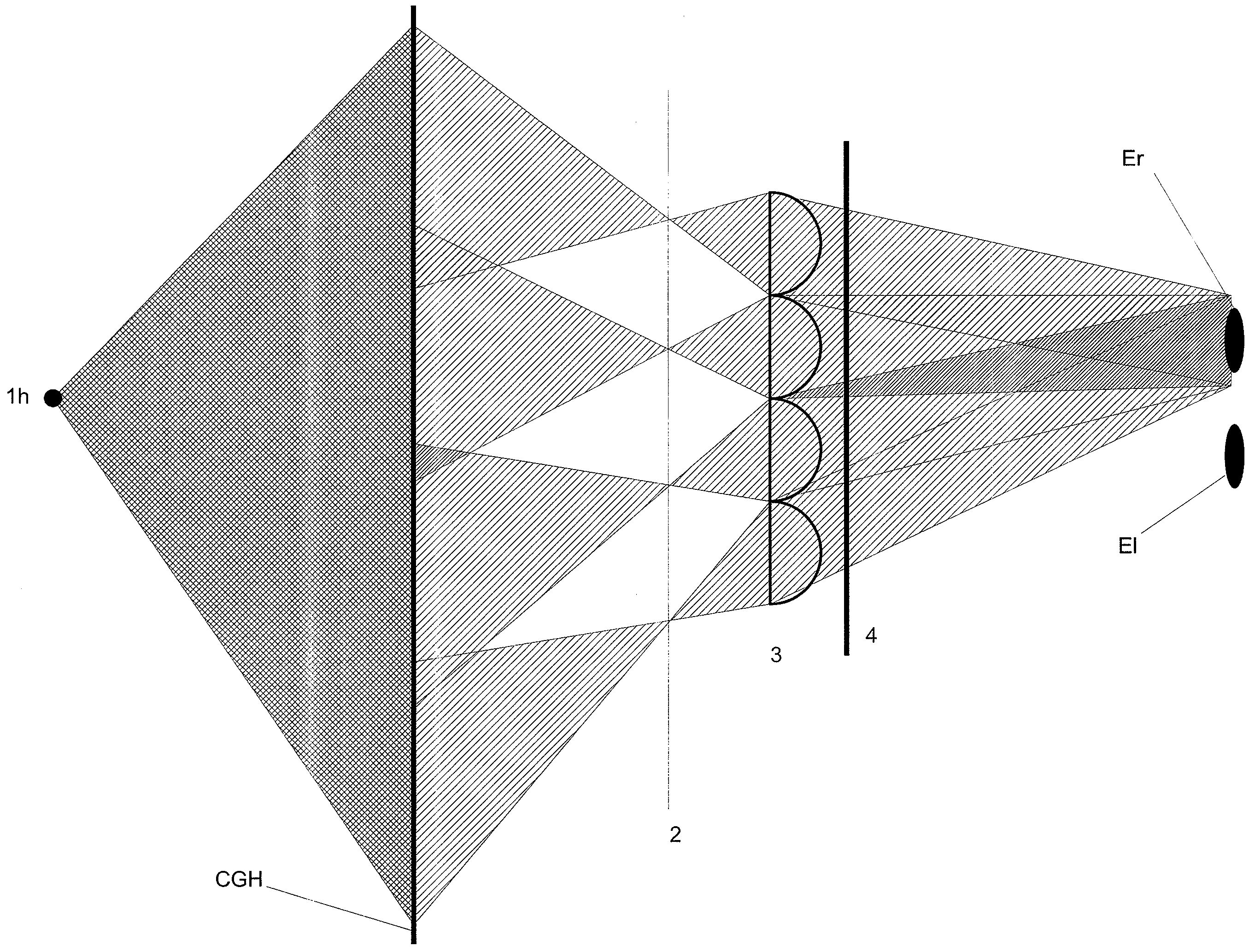
[0026]Now, the controllable illumination device according to this invention will be described with the help of an autostereoscopic display with a lenticular as imaging matrix, where the image information is sequentially provided by the reproduction matrix. If the autostereoscopic display is a multi-user display and if the illumination matrix contains for example line shaped light sources which illuminate the reproduction matrix and which direct bundles of rays on to viewers' eyes, further line shaped light sources will be required for further viewers' eyes in addition to the line shaped light sources for the left and right eye of the first viewer. Such type of illumination is realised with the help of the solution according to this invention.

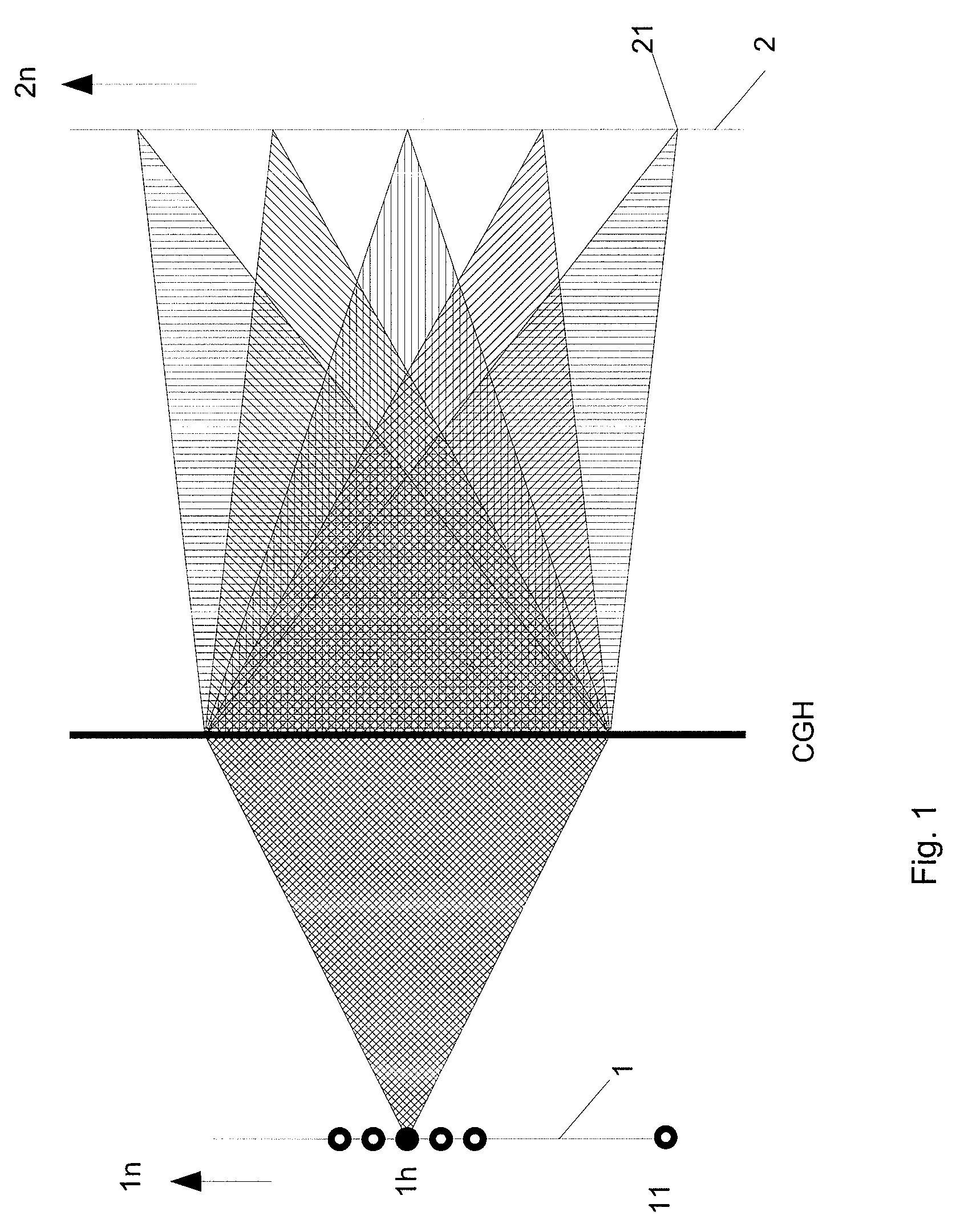
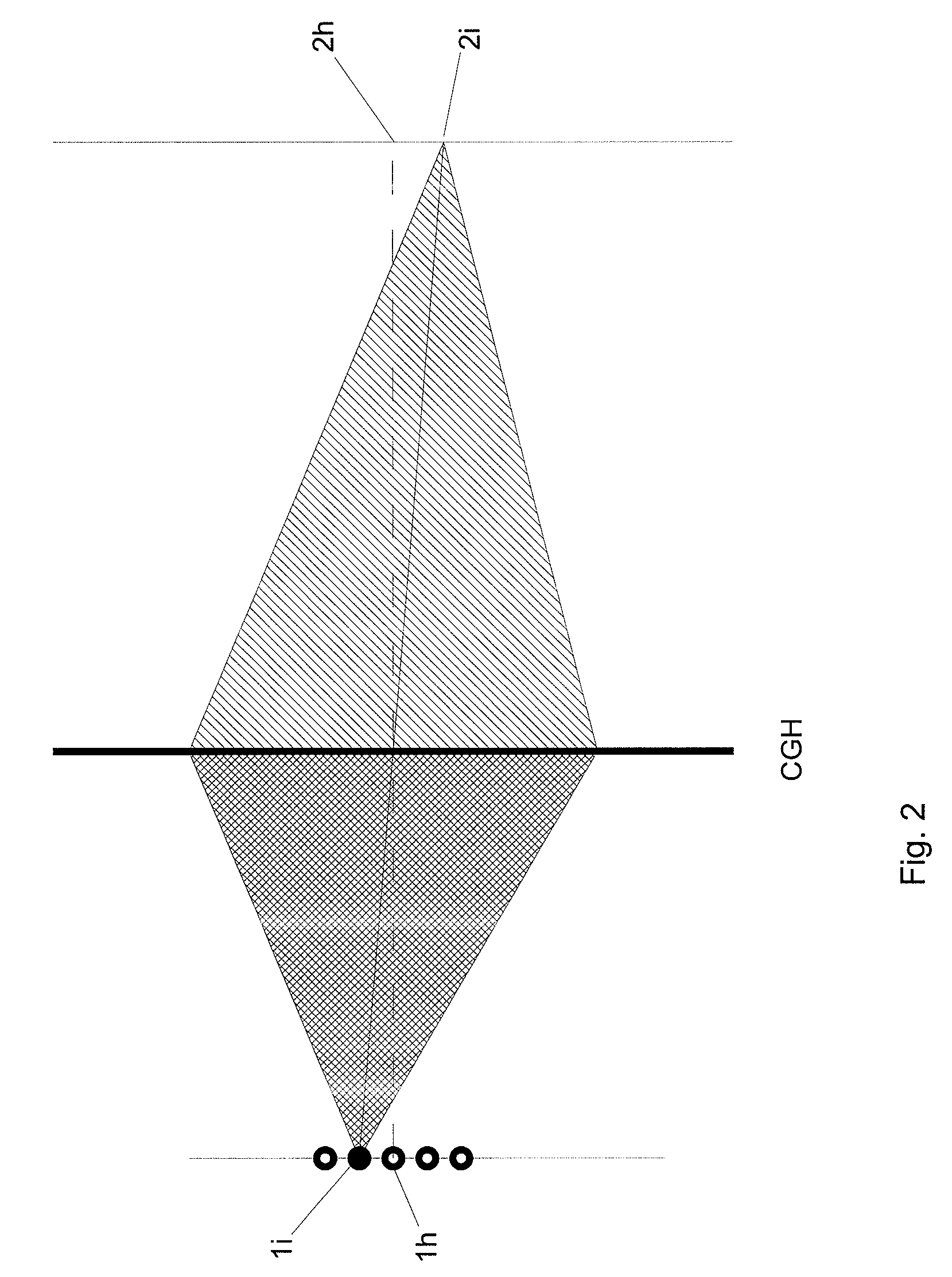
[0027]FIG. 1 shows schematically a detail of the controllable illumination device according to this invention. Specifically, it shows a part of the matrix of primary light sources 1, a part of the light modulator (SLM) in which a partial hologra...


PUM


Abstract

The invention relates to a controllable illumination device for an autostereoscopic or holographic display, which illumination device contains an illumination matrix of primary light sources having at least one luminous element per light source and a controllable light modulator (SLM) and a reproduction matrix. A computer-generated hologram (CGH) illuminated by the primary light sources (11, . . . , 1n) is coded on the controllable light modulator (SLM) and generates, in at least one plane downstream of the SLM, a matrix—reconstructed from the computer-generated hologram (CGH)—of secondary light sources (2) having a secondary light distribution for the purpose of illuminating the reproduction matrix (4) and for the purpose of focussing in light bundles onto each eye of the viewer via an imaging matrix. The CGH is calculated and reconstructed on the basis of the number of and the positions of the viewers and the system parameters. Owing to the reconstruction of the secondary light sources in a plurality of planes, it is possible for the image information of the display to be tracked for the viewers not only in the case of lateral movements but also in the axial direction.

Description

CROSS REFERENCE TO RELATED APPLICATIONS[0001]This application claims the priority of PCT / DE2006 / 000709 filed on Apr. 25, 2006 and DE 10 2005 021 155.0 filed on Apr. 29, 2005, the entire contents of which are hereby incorporated in total by reference.BACKGROUND OF THE INVENTION[0002]This invention relates to a controllable illumination device which consists of an illumination matrix with a backlight of primary light sources and a controllable light modulator, whereby an imaging matrix projects the light of said light modulator in bundles through a reproduction matrix, which it permeates full with light, on to at least one viewer. The reproduction matrix can be a stereoscopic or holographic display which contains monoscopic or stereoscopic information. The primary light sources may be point shaped light sources, line shaped light sources or area shaped light sources with at least one light-emitting element per light source.[0003]Displays for 2D representations typically comprise a so-...

Claims


Application Information

Patent Timeline
IPC IPC(8): G03H1/02
CPCG02B5/32G02B27/225G03H1/2286G03H1/2294G03H1/0005G03H2001/0212G03H2222/34G03H2223/19H04N13/32G02B30/26H05B47/10
Inventor HAUSSLER, RALFSCHWERDTNER, ARMIN
Owner SEEREAL TECHNOLOGIES
Learn More