Debris separator

a technology of dust separator and perforation, which is applied in the direction of liquid degasification, separation process, auxillary pretreatment, etc., can solve the problems of reducing the efficiency of the grill and therefore, the device, and the debris is subject to being drawn through the perforation for a relatively long time and distance, so as to achieve rapid and effective separation

Inactive Publication Date: 2012-12-25
MANSKA WAYNE E
View PDF17 Cites 20 Cited by
  • Summary
  • Abstract
  • Description
  • Claims
  • Application Information

AI Technical Summary

Benefits of technology

[0015]The present invention is a device that rapidly and effectively separates, removes and collects debris particulates such as sawdust and wood shavings from airflow between a debris source such as a woodworker's power tool and a vacuum source such as a shop-vac.
[0020]Accordingly, it is an object of the present invention to provide a debris separator having a first chamber that effectivly separates and removes a higher percentage of debris from airflow.
[0021]Another object of the invention is to provide a debris separator that employs forces other that gravity to rapidly remove debris from airflow so that it does not dwell adjacent an outlet.

Problems solved by technology

However, adjacent and below the outlet any downward movement of the air ceases and any subsequent downward movement of the debris is solely due to gravity.
Due to the relatively large height and diameter of the lower perforated portion the debris is subject to being drawn through the perforations for a relatively long time and distance.
In which case clogging of the perforations could occur which would reduce the efficiency of the grill and therefore, the device.
It is apparent the geometries and proximities of the key elements of first and second chambers of Oh's device simply do not effect sufficient removal of debris, and that the device relies on the third chamber to complete the job.
Although Oh's device may function to remove a large percentage of the particulate matter from the incoming airflow, it does have certain drawbacks.
Primarily, it is quite complicated and has many parts that would be expensive to produce and assemble.
It also has a multitude of small spaces and crevices where dust may accumulate that would be difficult to access and clean.
In either case, since the debris is often of small size and low specific gravity, its presence in the first chamber is prolonged making it more susceptible to being drawn into the outlet port.
The Witter, Oh, Thien and other prior-art devices have a common deficiency.
And since the debris is often of small size and low specific gravity some dwells below the outlet for sufficient time that it is drawn by the vortex into the outlet and not collected as intended.

Method used


Image

  • Debris separator
  • Debris separator
  • Debris separator

Examples


Embodiment Construction

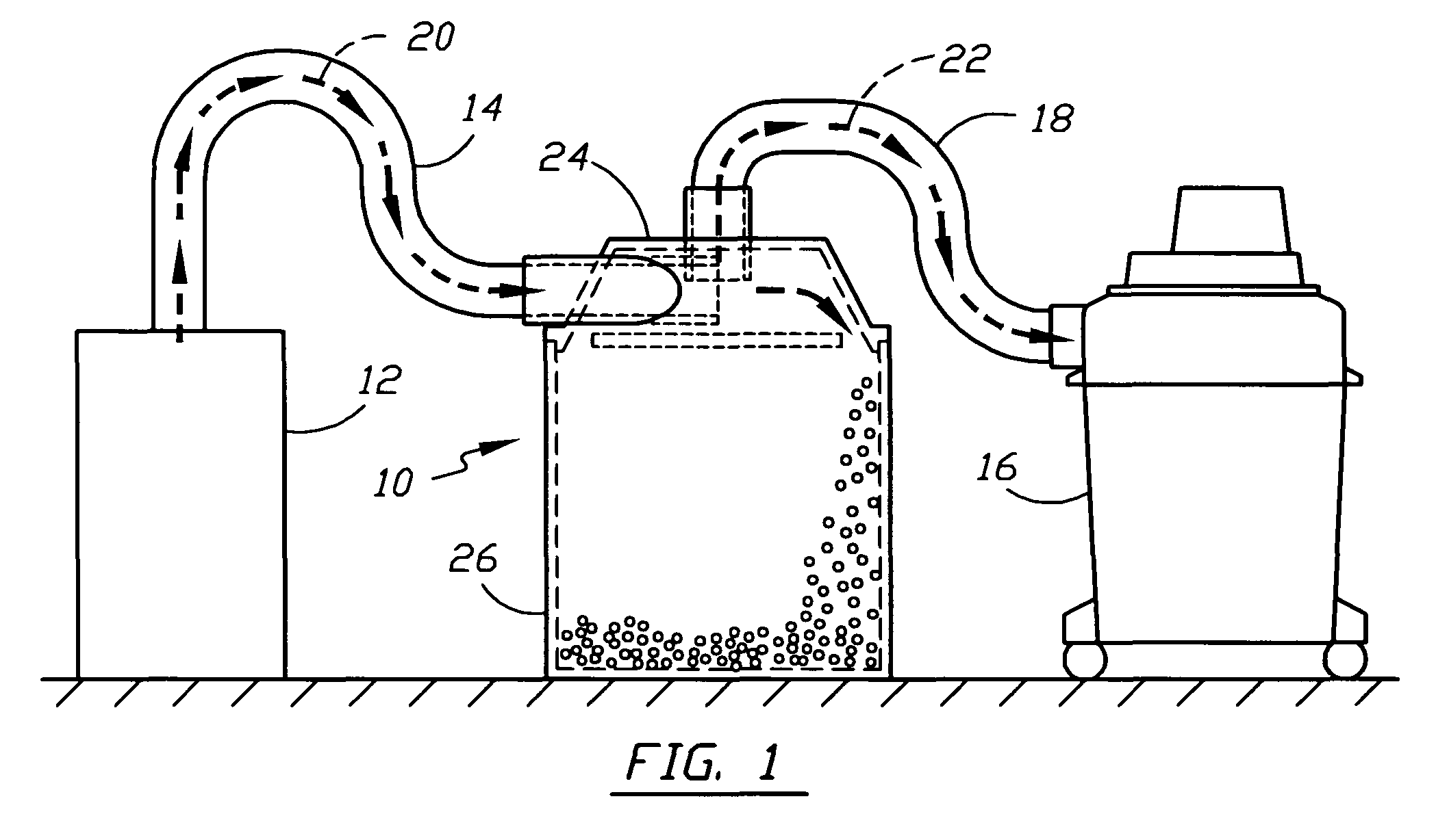
[0041]Referring now to the drawings, there is shown in FIG. 1 a debris separator 10 of the present invention connected to a debris source 12 by a first conduit 14, and also to a vacuum source 16 by a second conduit 18. The first conduit 14 conveys debris-borne airflow 20 to the debris separator 10 while the second conduit 18 conveys substantially cleaned airflow 22 to the vacuum source 16. The debris source 12 may be, for example, a woodworker's power tool such as a table saw, or simply a pile of rubble. The debris separator 10 comprises a first chamber 24 and a second chamber 26 that is situated below the first chamber 24. The first chamber 24 functions to separate debris from the debris-borne airflow 20. The second chamber 26, which may be a commonly available pail or trashcan, functions to collect the separated debris.

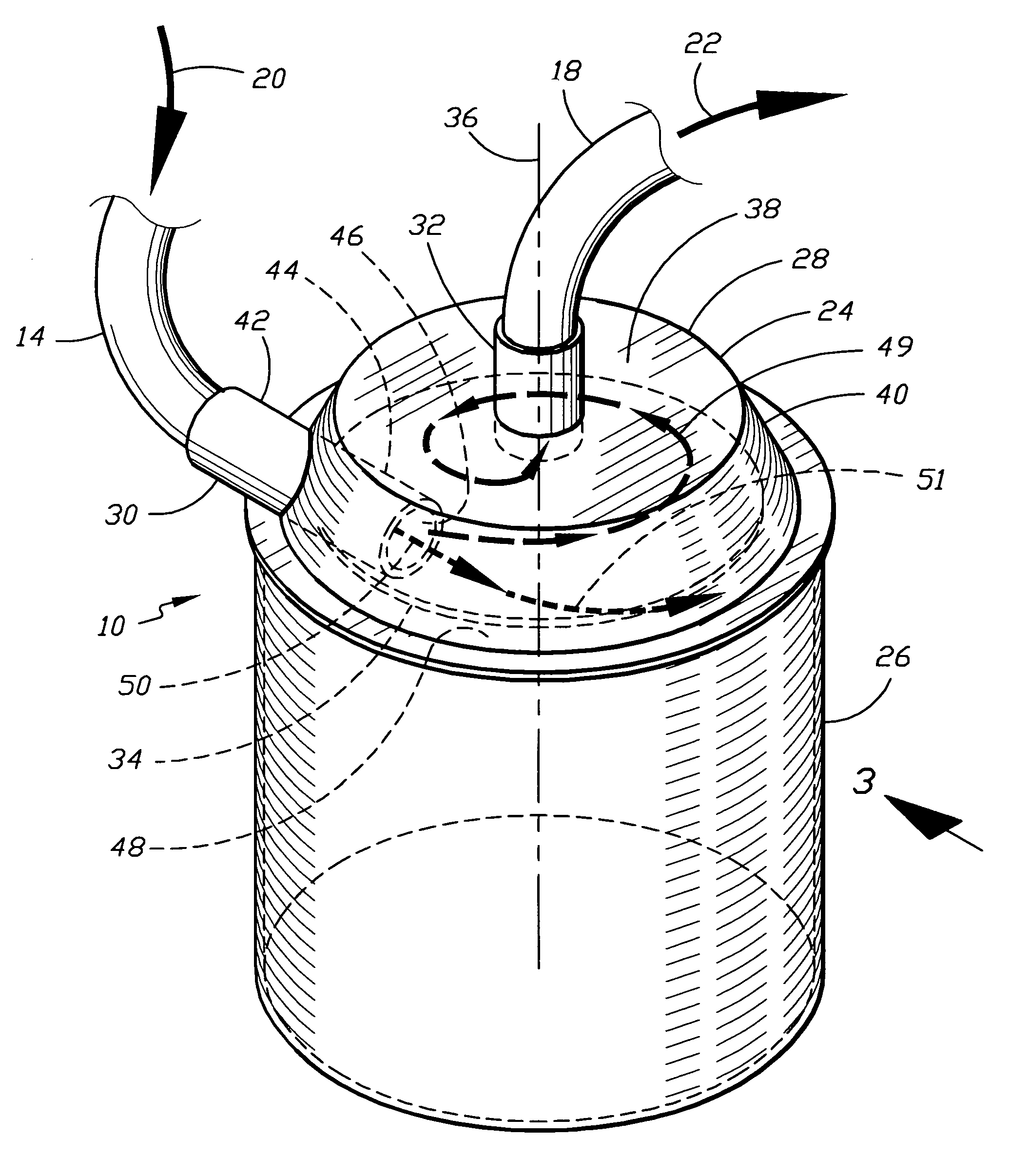
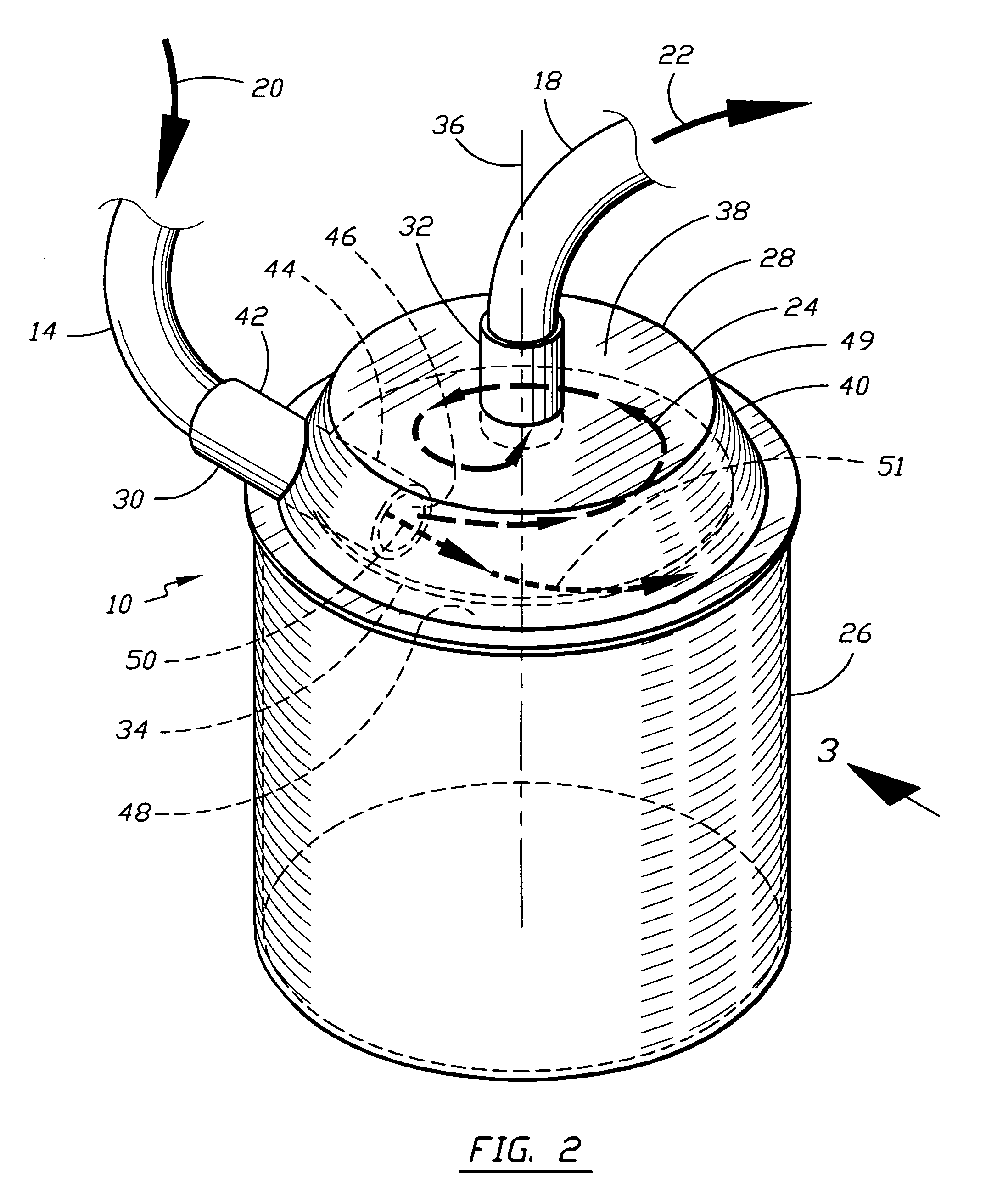
[0042]FIG. 2 illustrates a preferred embodiment of the debris separator 10 shown in FIG. 1 whereby the first chamber 24 comprises a shroud 28, an input port 30, an ...


PUM

PropertyMeasurementUnit
pressureaaaaaaaaaa
forceaaaaaaaaaa
arc distanceaaaaaaaaaa

Abstract

The present invention is a device that rapidly and effectively separates and collects debris from airflow between a debris source and a vacuum source. The device comprises a first chamber situated above and adjoining a second chamber. The first chamber functions to separate and remove the debris and the second chamber functions to collect the debris. The first chamber is circular in cross-section and comprises an upper portion and a downward and outward sloping sidewall. The upper portion has an output port connected by a first conduit to the vacuum source and the sidewall has an input port connected by a second conduit to the debris source. Air and debris are drawn into the first chamber through the input port by suction created at the output port. The debris is centrifugally forced to the sidewall whereby it is then centripetally forced downward into the second chamber through a peripheral opening between the sidewall and a barrier, while cleaned air is evacuated through the output port.

Description

CROSS REFERENCE TO RELATED APPLICATIONS[0001]Not ApplicableSTATEMENT REGARDING FEDERALLY SPONSORED RESEARCH AND DEVELOPMENT[0002]Not ApplicableBACKGROUND OF THE INVENTION[0003]The present invention relates to dust separators and collectors commonly used by wood workers to separate and collect debris composed of particulates such as sawdust and shavings created by debris sources; i.e. power tools such as saws, sanders, jointers, routers, etc. Certain types of dust collectors generally comprise two chambers having an opening therebetween. The first chamber functions to separate the debris from an airflow created by a vacuum source such as a shop-vac. The second chamber, which is situated below the first chamber, collects the debris that falls by gravity therein through the opening. Dust collectors are situated between the debris source and the vacuum source and function to remove as much of the debris as possible before it enters the vacuum source. This retards clogging of the vacuum'...

Claims


Application Information

Patent Timeline
Patent Type & Authority Patents(United States)
IPC IPC(8): B01D45/00
CPCA47L7/0071B01D45/16B04C5/103B04C5/187
Inventor MANSKA, WAYNE E.
Owner MANSKA WAYNE E
Why Eureka
Try Eureka