
Articulating arm for medical procedures

a technology of articulating arms and medical procedures, applied in the field of articulating arms for medical procedures, can solve the problems of inconvenient non-invasive procedures, manipulator arms not suited for carrying or maneuvering heavy objects, and few robotic arms with delicate and intricate movement ability

Inactive Publication Date: 2012-12-25
LIPOSONIX
View PDF91 Cites 317 Cited by
  • Summary
  • Abstract
  • Description
  • Claims
  • Application Information

AI Technical Summary

Problems solved by technology

There are few robotic arms having the delicate and intricate movement ability as is demanded and required in medical procedures.
However such manipulator arms are not suited for carrying or maneuvering heavy objects.
However these devices are not suited for noninvasive procedures.
Some arms used for providing industrial measurement of solid objects provide limited forms of counter weighting and position encoders, however these devices are not designed for carrying any sort of substantial loads, nor do they provide for any form of adaptive positioning.

Method used


Image

  • Articulating arm for medical procedures
  • Articulating arm for medical procedures
  • Articulating arm for medical procedures

Examples


second embodiment

[0038]In a second embodiment, there is a system for the positioning of a medical device, the system comprising a robotic arm and a control means for controlling the robotic arm. There is a medical device fixedly positioned within a therapy head with the therapy head being movably connected to the robotic arm. There is an electronic controller for translating the instructions received from the control means, and relaying the movement instructions to the robotic arm. An artificial wobble may be automatically introduced to the movement instructions to the robotic arm.

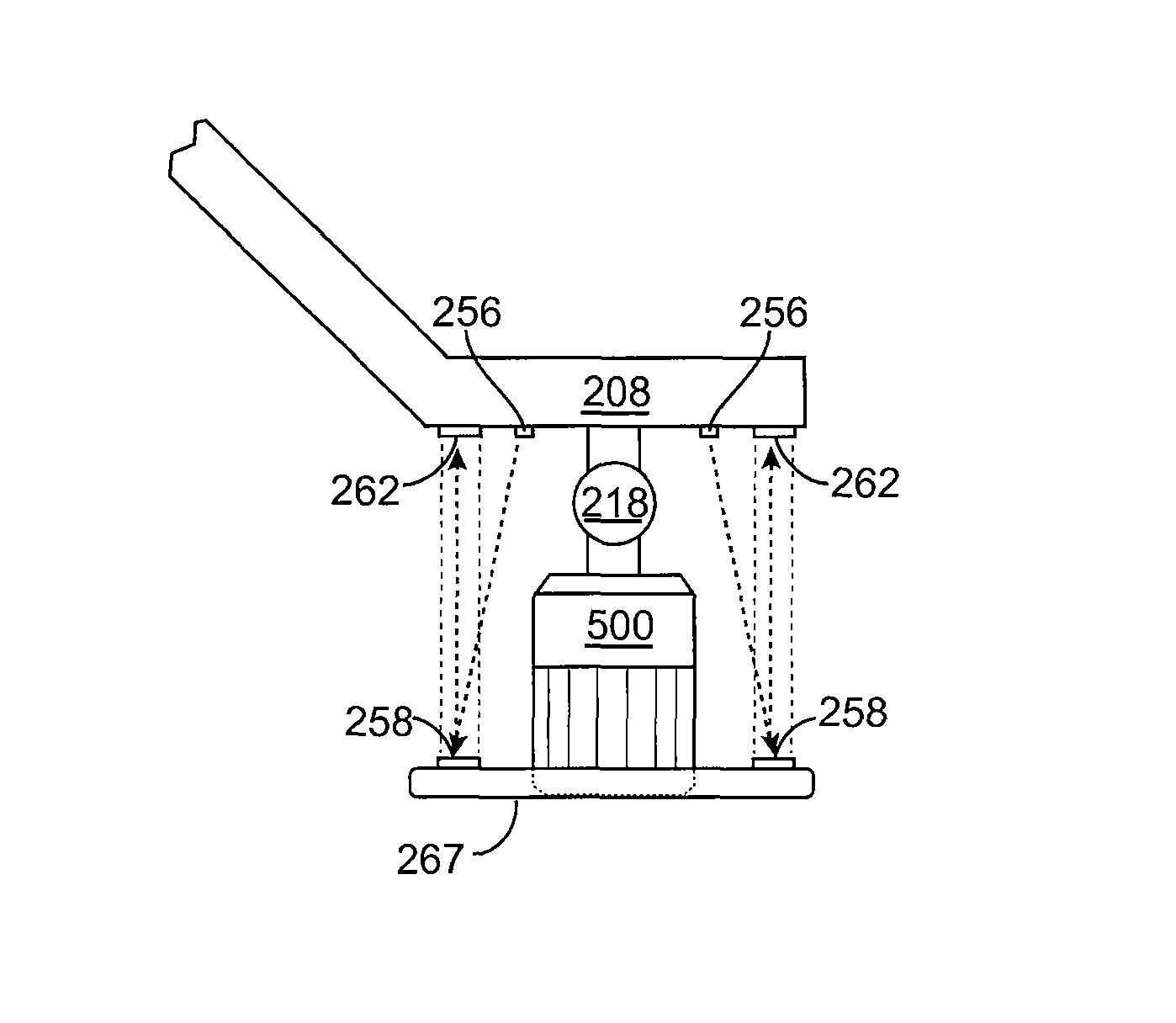
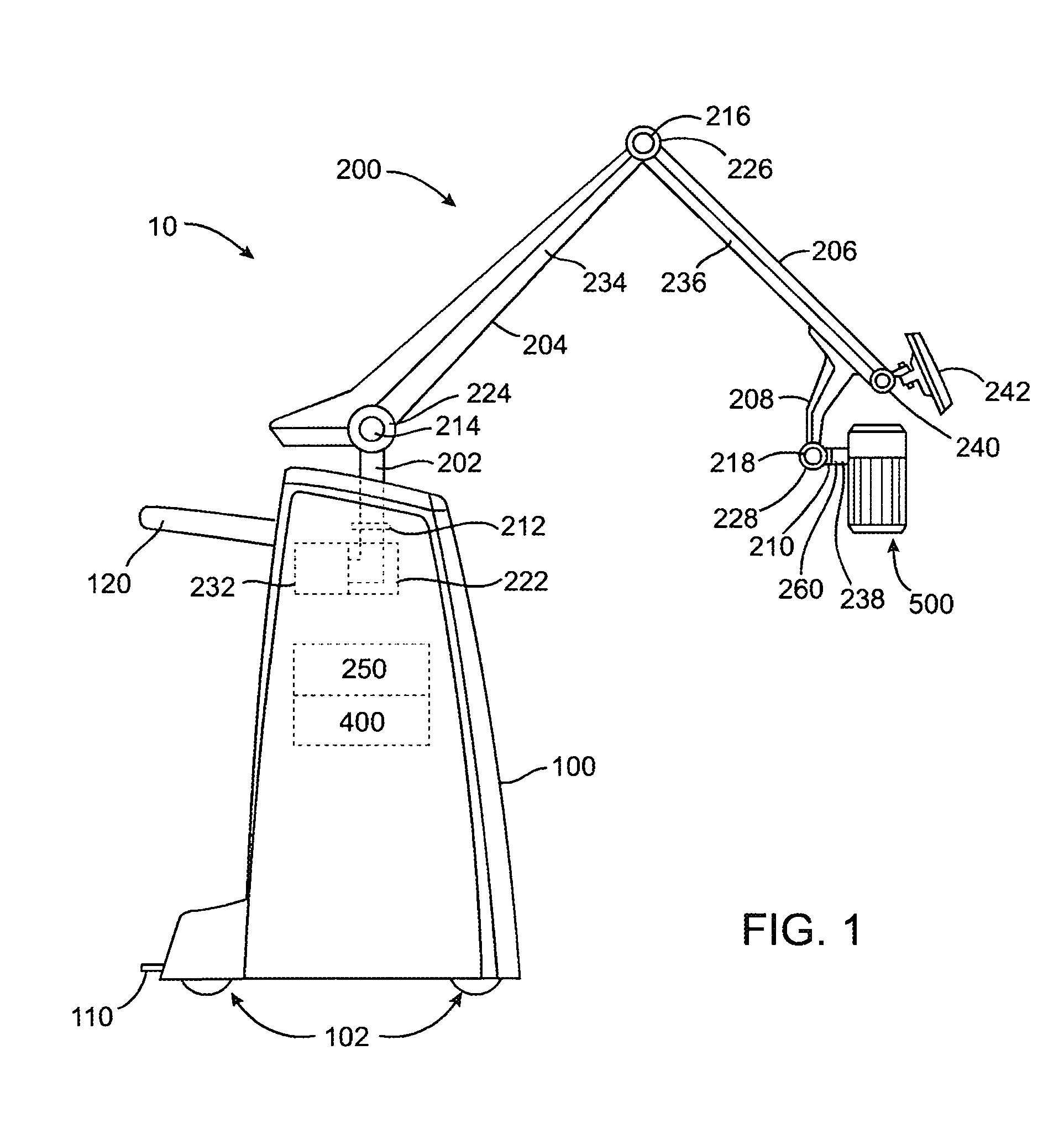
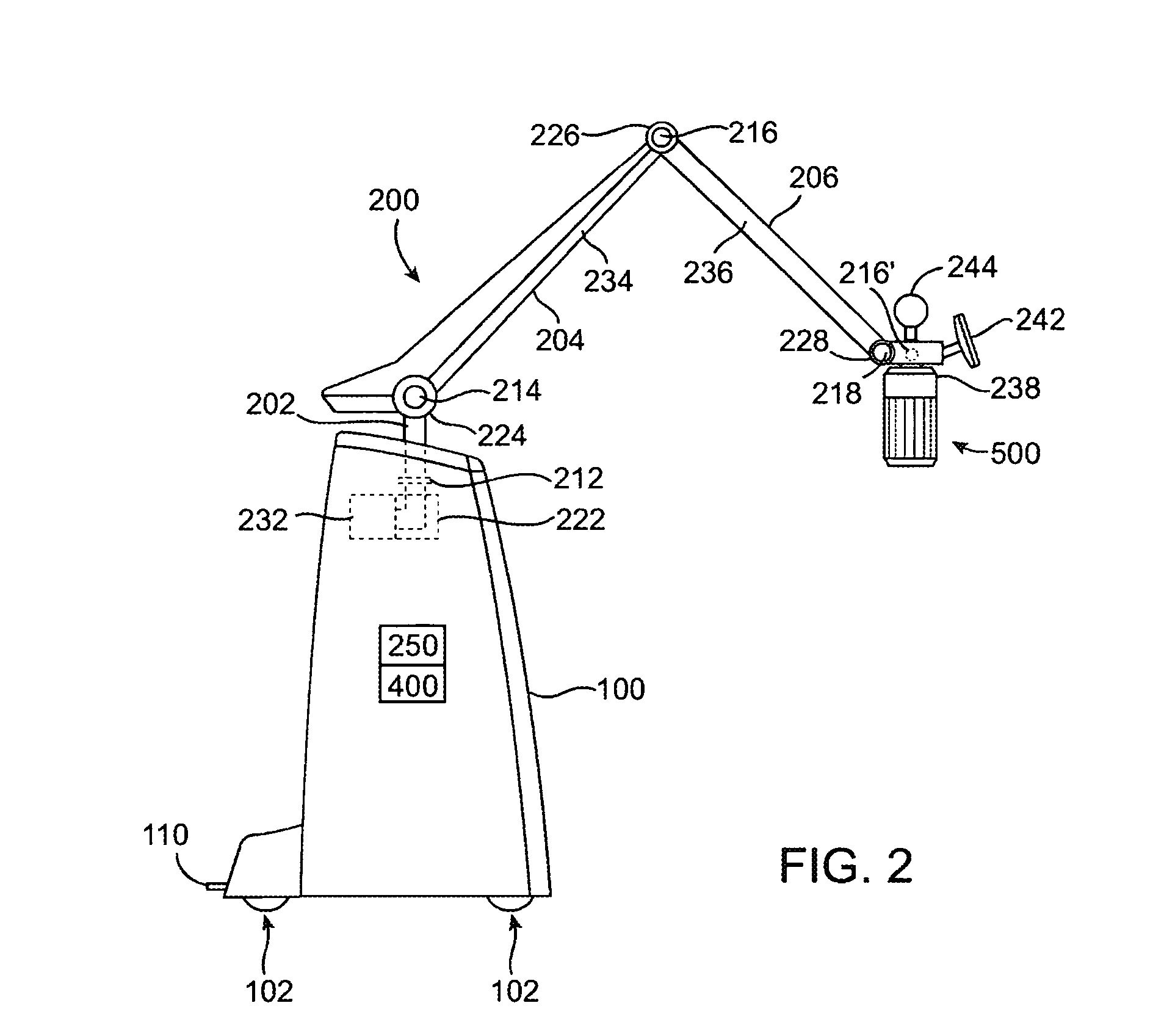
[0039]The robotic arm described herein has been previously described in parent U.S. application Ser. No. 10 / 751,344. The contents of which are herein incorporated by reference. The robotic arm is used to carry a therapy device and maintain the position of the therapy device relative to a patient body. The therapy head is potentially too heavy for a user to support the weight of it for the length of a medical procedure with...

first embodiment

[0042]The first control means may be a variety of different devices capable of guiding the movement of the robotic arm. In the first control means, a computer input device can be used to provide both virtual positioning of the therapy head, and movement instructions to the robotic arm. The computer input device may be any of a class of input device normally used to provide movement commands to a pointer (cursor) on a computer screen. These are in general two dimensional input devices such as a mouse, tablet device or trackball. In addition three dimensional input devices can be used to provide virtual positioning in a three dimensional visual frame on a computer screen. Such devices are commonly exemplified in joysticks, D-controllers and the like. Finally true freedom on movement in a virtual environment can be provided by a six degree of freedom (DOF) device, such as a “spaceball” input device commonly used in Computer Aided Design (CAD) applications. The input device used as the ...


PUM


Abstract

A two-stage control system is disclosed being made of a first control means for providing command and control of a robotic arm, and a second control means for the control and movement of a therapy device, such as an ultrasound transducer. The therapy device is positioned within a therapy head. The therapy head is attached to the distal end of the robotic arm. The two-stage control system provides for a macro and micro level of control for the therapy device during a therapy procedure.

Description

CROSS-REFERENCES TO RELATED APPLICATIONS[0001]The subject matter of the present application is a continuation-in-part of U.S. patent application Ser. No. 10 / 751,344, filed Dec. 30, 2003, entitled “Articulating Arm for Medical Procedures”; and related to the following application Ser. No. 11 / 026,519, filed on the same day as the present application, entitled “Systems and Methods for the Destruction of Adipose Tissue”; Ser. No. 10 / 750,370, entitled “Medical Device Inline Degasser”; Ser. No. 10 / 750,369, entitled “Disposable Transducer Seal”; 60 / 533,528, entitled “Position Tracking Device”; 60 / 533,988, entitled “Method for Planning and Performing Ultrasound Therapy”; 60 / 534,036, entitled “Ultrasound Therapy Head with Movement Control”; 60 / 533,958, entitled “Systems and Methods for the Destruction of Adipose Tissue”; 60 / 534,034, entitled “Component Ultrasound Transducer”; 60 / 630,857, entitled “Systems and methods for the destruction of adipose tissue”; the full disclosure of each of thes...

Claims


Application Information

Patent Timeline
Patent Type & Authority Patents(United States)
IPC IPC(8): A61B8/00A61N7/00A61B5/05A61B19/00A61N7/02B25J9/00
CPCA61B5/6843A61B8/00A61B8/4218A61B19/2203A61B2019/2223A61B2019/2292A61B2019/5229A61B2019/5276A61N7/02A61N2007/0008A61B34/30A61B34/37A61B34/76A61B2090/372A61B2090/378
Inventor QUISTGAARD, JENS U.ETCHELLS, TIMDARLINGTON, GREGORY PAULDESILETS, CHARLES S.
Owner LIPOSONIX
Learn More