Optical transmission system and multi-core optical fiber
a transmission system and optical fiber technology, applied in the direction of optical elements, cladded optical fibres, instruments, etc., can solve the problem of bending loss particularly high, and achieve the effect of improving bending loss
- Summary
- Abstract
- Description
- Claims
- Application Information
AI Technical Summary
Benefits of technology
Problems solved by technology
Method used
Image
Examples
first embodiment
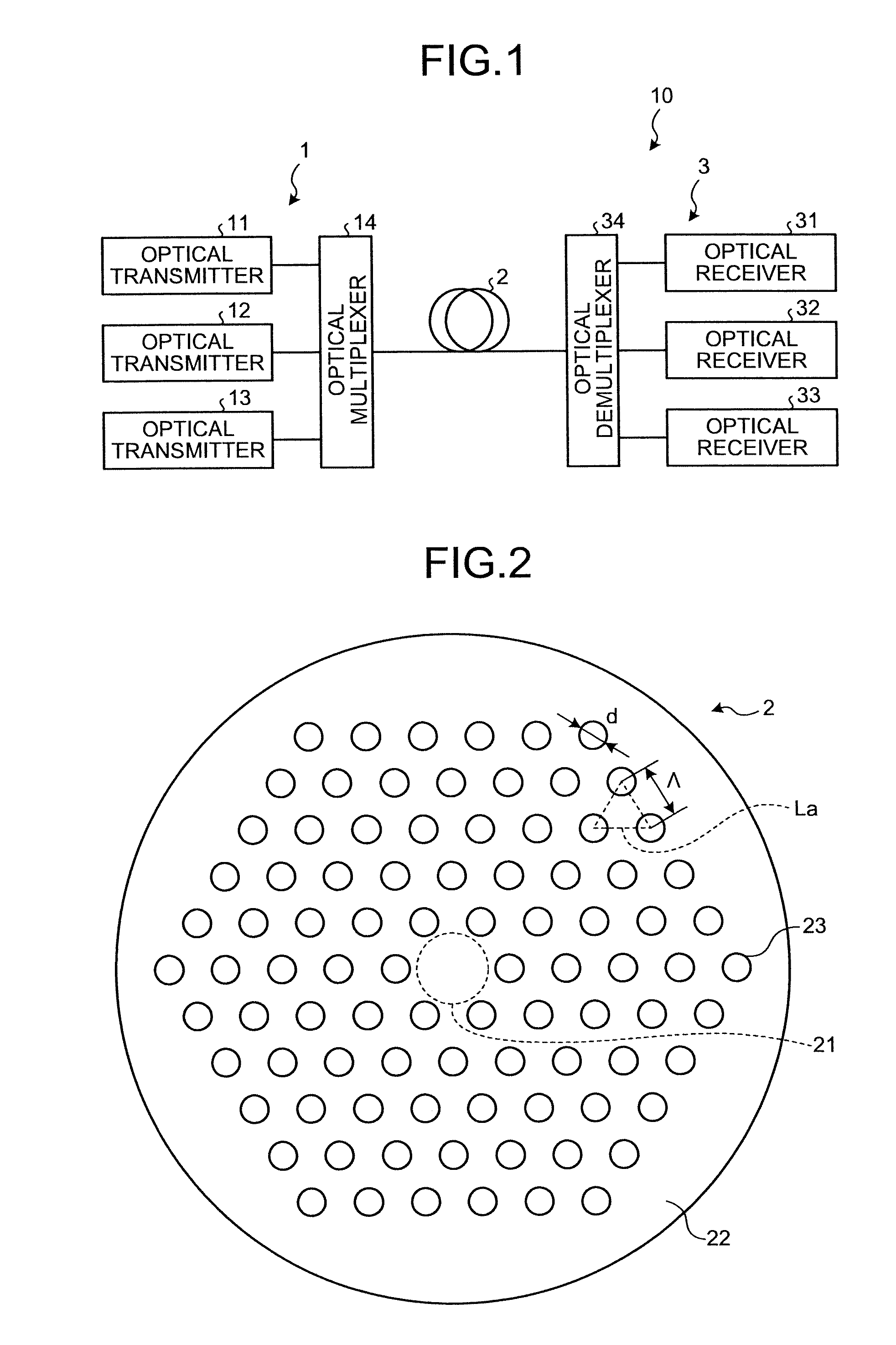
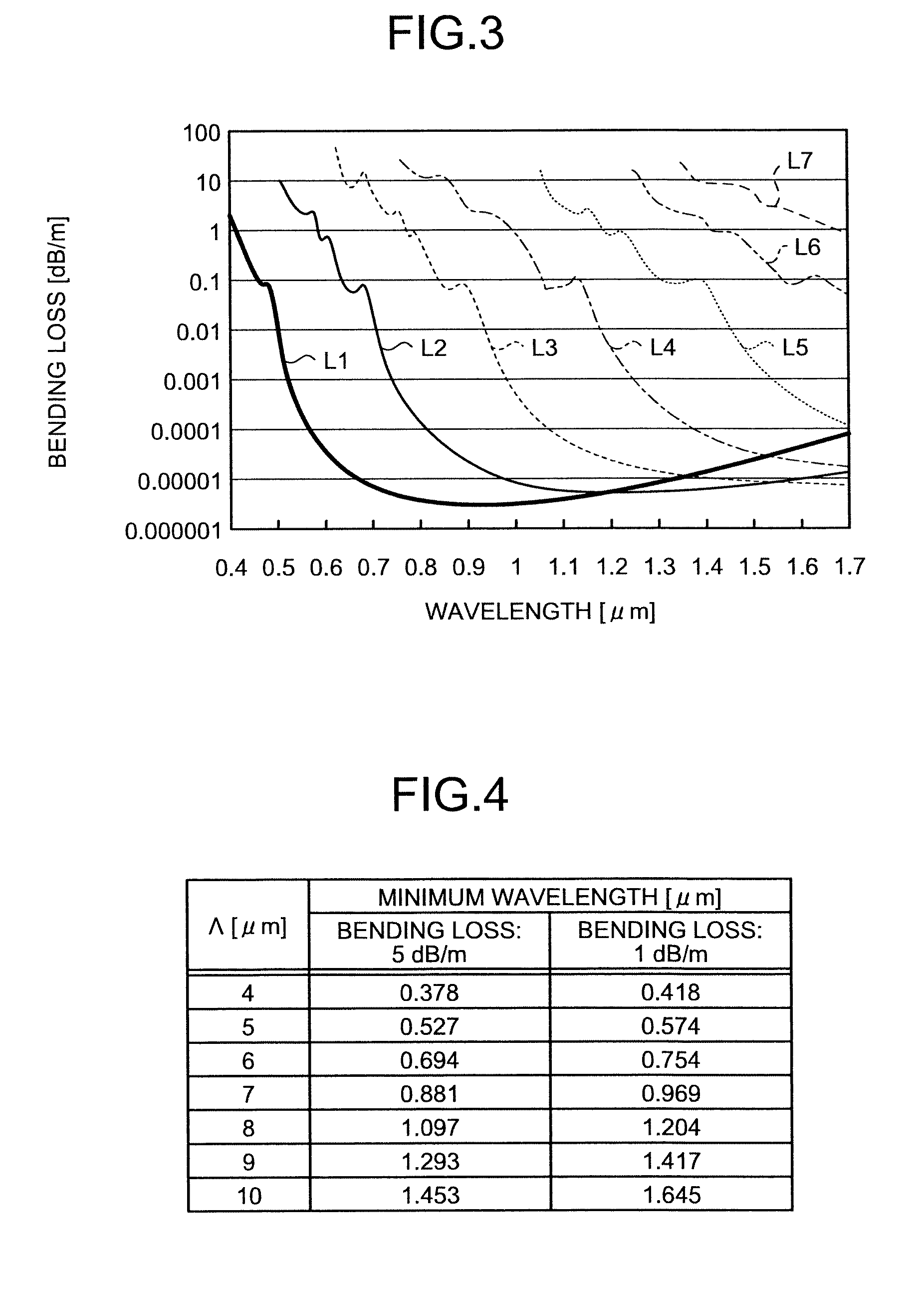
[0069]The line L8 shown in FIG. 5 specifies the minimum wavelength where the bending loss becomes equal to or less than 5 dB / m. Therefore, in the manner if Λ is set for the HF 2 correspondingly to λs that is the minimum wavelength within the operation wavelength band so that Λ≦−0.518λs2+6.3617λs+1.7468 is established, it is possible to make the bending loss equal to or less than 5 dB / m at the wavelength of each of the optical signals.
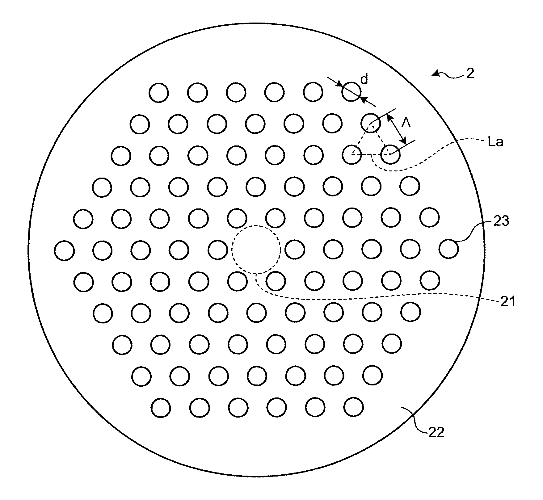
[0070]In the HF 2 according to the first embodiment, d / Λ is 0.43; however, the present invention is not limited to this value, and the ESM characteristic can be realized with a value less than 0.43. FIG. 6 is a schematic of a relationship between Λ and the minimum wavelength where the bending loss becomes 1 dB / m when d / Λ is 0.40, 0.43, 0.48, and 0.50 in an HF having the same structure as one shown in FIG. 2. Lines L10 to L13 are curves representing the relationship when d / Λ is 0.40, 0.43, 0.48, and 0.50, respectively. As shown in FIG. 6, when d / Λ becom...
second embodiment
[0107]The crosstalk can also be improved by applying a lateral pressures to the multi-core HF, in the same manner by applying a bend thereto. FIG. 37 is a schematic of an exemplary lateral pressure applying unit included in the optical transmission system 20 according to the Lateral pressure applying members 8, which are the lateral pressure applying unit, include two board-like members 8a and 8b made of metal or resin, for example. These board-like members 8a and 8b hold the multi-core HF 5, wound one or more times at a diameter of 20 millimeters, therebetween to apply lateral pressures to the multi-core HF 5. In this manner, the crosstalk between the cores of the multi-core HF 5 can be improved, in comparison with that without the lateral pressure applying members 8.
[0108]The bobbin 7 or the lateral pressure applying members 8 may be provided in a singularity, or in a plurality separated from each other by a predetermined distance, in one section of the optical circuit, that is b...
third embodiment
[0113]Assuming that, in the multi-core HF shown in FIG. 33, the cores that are three-fold rotational symmetric around the center axis of the cladding are in a standard arrangement, only the core X is arranged at a position offset from the standard arrangement. As a result, a core of the multi-core HF can be advantageously connected easily upon connecting a specific core thereof to a specific core of another multi-core HF or to an optical apparatus by way of fusion splicing, connector, or mechanical splicing. The multi-core HF having such an offset core will now be explained specifically under the present invention.
[0114]FIG. 38 is a schematic sectional view of a multi-core HF 5a according to the third embodiment. The multi-core HF 5a is different from the multi-core HF 5 in that a core 512a, corresponding to the core 512 of the multi-core HF 5 shown in FIG. 26, is offset from the position of the core 512 by the lattice constant Λ toward the side of the core 511. The other cores 511,...
PUM
 Abstract
Description
Claims
Application Information
 - Generate Ideas
- Intellectual Property
- Life Sciences
- Materials
- Tech Scout
- Unparalleled Data Quality
- Higher Quality Content
- 60% Fewer Hallucinations
Browse by: Latest US Patents, China's latest patents, Technical Efficacy Thesaurus, Application Domain, Technology Topic, Popular Technical Reports.
© 2025 PatSnap. All rights reserved.Legal|Privacy policy|Modern Slavery Act Transparency Statement|Sitemap|About US| Contact US: help@patsnap.com


