
Optical pickup apparatus

a technology of optical pickup and optical pickup head, which is applied in the direction of optical recording head, instruments, data recording, etc., can solve the problems of increasing the number of parts needed for the optical pickup apparatus, affecting the proper operation of the focus servo using the differential astigmatism method, and affecting the quality of the optical pickup apparatus. , to achieve the effect of reducing the number of parts

Inactive Publication Date: 2012-12-18
SANYO ELECTRIC CO LTD
View PDF3 Cites 0 Cited by
  • Summary
  • Abstract
  • Description
  • Claims
  • Application Information

AI Technical Summary

Benefits of technology

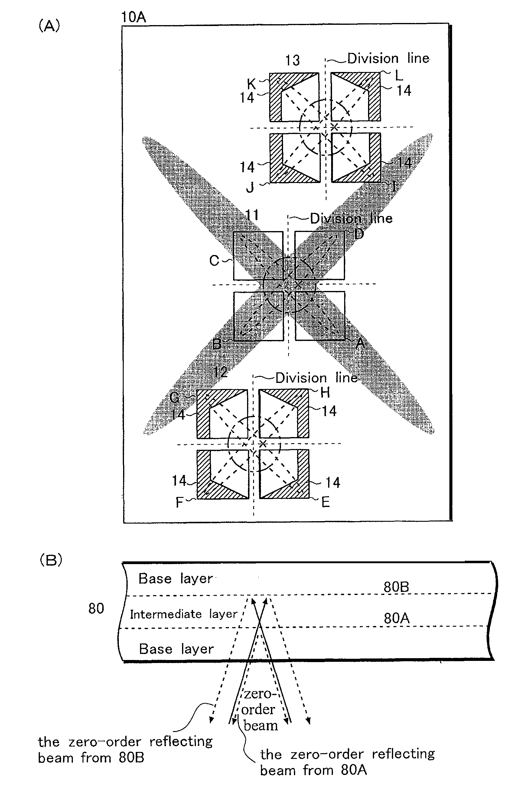
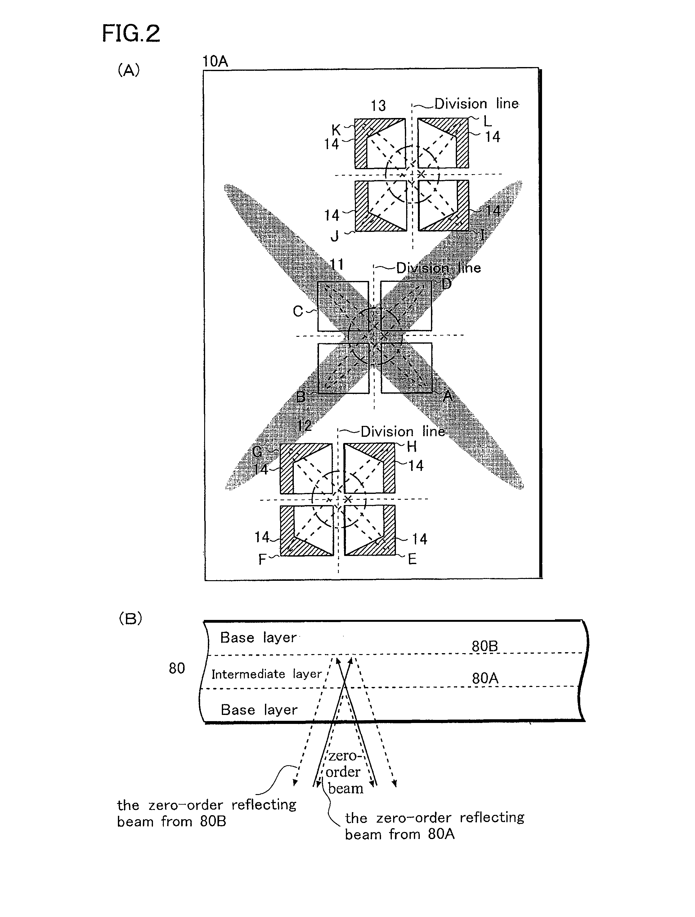
The present invention aims to provide an optical pickup apparatus that uses a reduced number of parts. The apparatus includes a first laser unit, a second laser unit, and a photo detecting device. The first and second laser beams are emitted from the first laser unit, while the third laser beam is emitted from the second laser unit. The first laser beam, second laser beam, and third laser beam are guided to a common optical path by a beam splitter and are directed to various information recording media. The photo detecting device includes a first light receiving region for receiving a zero-order beam, a second light receiving region for receiving a plus first-order beam, and a third light receiving region for receiving a minus first-order beam. The apparatus also includes a light-reception prohibiting area for rejecting the reception of the laser beam. The technical effect of this invention is to simplify the optical pickup apparatus and reduce the number of parts needed for its operation.

Problems solved by technology

Once this phenomenon takes place, the outputs from the light receiving portions I′, G′ become greater than their respective expected values, and the focus servo operation using the differential astigmatism method is hindered from being performed appropriately.
For this reason, this problem becomes conspicuously serious.
This entails another problem of the increase in the number of parts needed for the optical pickup apparatus.

Method used


Image

  • Optical pickup apparatus
  • Optical pickup apparatus
  • Optical pickup apparatus

Examples


Embodiment Construction

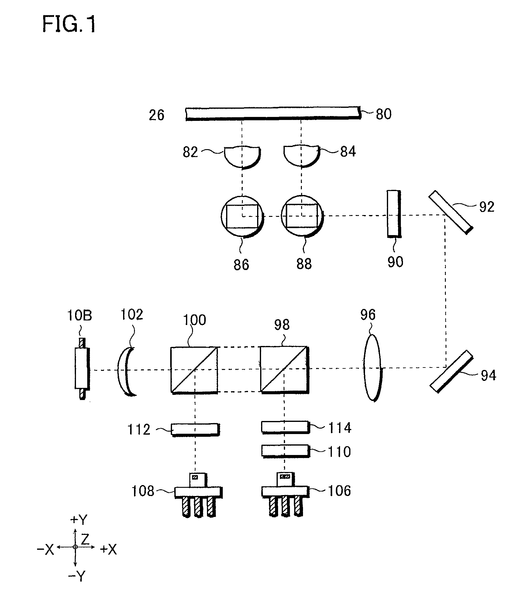
[0024]Referring to FIG. 1, description is provided for a configuration of optical elements in an optical pickup apparatus 26 including a PDIC 10B.

[0025]The optical pickup apparatus 26 has a function of: focusing laser beams, which respectively comply with the BD (blu-ray disc) standards, the DVD (digital versatile disc) standards or the CD (compact disc) standards, on an information recording layer of an optical disc (an information recording medium); and receiving beams which are reflected off the information recording layer; and converting the reflecting beams into the respective electric signals.

[0026]The laser beams used by the optical pickup apparatus 26 are a laser beam (in a bluish violet wavelength range of 400 nm to 420 nm) complying with the BD standards; a laser beam (in a red wavelength range of 645 nm to 675 nm) complying with the DVD standards; and a laser beam (in an infrared wavelength range of 765 nm to 805 nm) complying with the CD standards.

[0027]With regard to it...


PUM

PropertyMeasurementUnit
wavelength rangeaaaaaaaaaa
red wavelength rangeaaaaaaaaaa
infrared wavelength rangeaaaaaaaaaa

Abstract

Provided is an optical pickup apparatus using a reduced number of parts. An optical pickup apparatus (26) of the present invention includes: a laser unit (108) for emitting a laser beam complying with the BD standards; a laser unit (106) for emitting a laser beam complying with the DVD standards and a laser beam complying with the CD standards; and a PDIC (10B) for receiving and detecting the laser beams complying with the respective standards. Because the laser beam complying with the DVD standards and the laser beam complying with the BD standards are received by one photo detector provided in the PDIC (10B), the number of parts needed for the optical pickup apparatus (26) can be reduced, and the costs of the apparatus can be decreased.

Description

[0001]This application claims priority from Japanese Patent Application Number JP 2010-191944 filed on Aug. 30, 2010, the content of which is incorporated herein by reference in its entirety.BACKGROUND OF THE INVENTION[0002]1. Field of the Invention[0003]The present invention relates to an optical pickup apparatus. In particular, the present invention relates to an optical pickup apparatus using a reduced number of parts.[0004]2. Description of the Related Art[0005]In these days, CDs (compact discs), DVDs (digital versatile discs) and the like are widely in use as optical disc media for information recording / reproduction. In order to record / reproduce information in an optical disc medium, a laser beam to be collected by an objective lens needs to be precisely focused on an information recording layer included in the optical disc medium. To this end, some controls are performed. Examples of the controls include: a focusing control for correcting an error which takes place when the la...

Claims


Application Information

Patent Timeline
Patent Type & Authority Patents(United States)
IPC IPC(8): G11B7/00
CPCG11B7/131G11B7/133G11B7/0903G11B7/1353G11B7/1374G11B7/1378G11B2007/0006G11B2007/0013
Inventor HIRUMA, MITSUHIROASAKAWA, CHIAKI
Owner SANYO ELECTRIC CO LTD
Learn More