
Device for charging at least one electrical battery on board a boat

a technology for electric batteries and boats, which is applied in the direction of vessel auxiliaries, vessel construction, electric generator control, etc., can solve the problems of 4 volts out of the direct voltage machine, the number of revolutions of the axles is mostly too low, and the voltage is far too low to enable the charging of the battery

Inactive Publication Date: 2012-12-11
LARSSON
View PDF12 Cites 12 Cited by
  • Summary
  • Abstract
  • Description
  • Claims
  • Application Information

AI Technical Summary

Benefits of technology

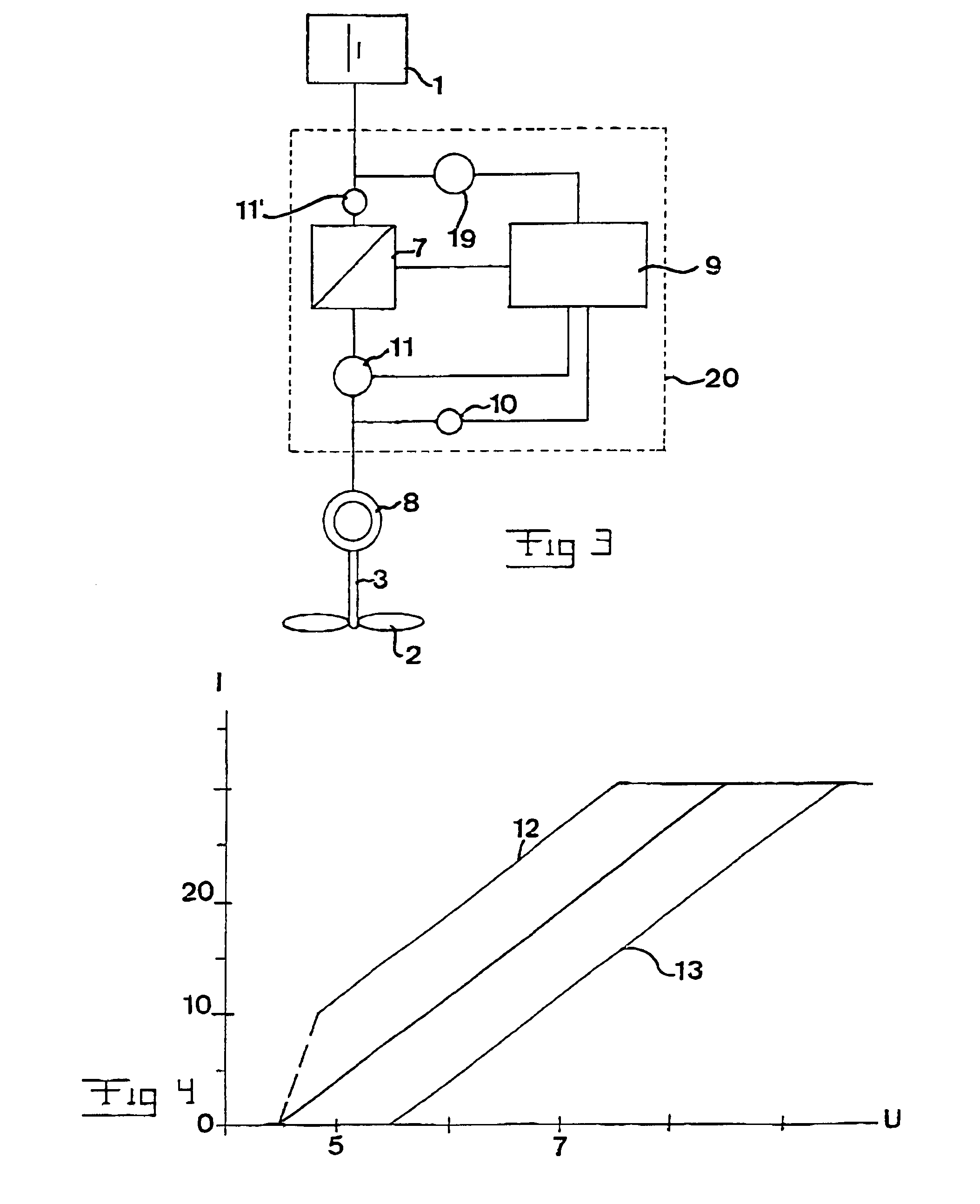
[0008]According to a preferred embodiment of the invention the electronic unit is adapted to calculate the maximum set value for the current out from the electric machine towards the battery on the basis of data concerning the voltage generated by the electric machine delivered by said member and control the DC / DC-converter to adjust the charging voltage to the battery for obtaining said maximum current set value. The battery may in this way be charged in an optimum way, since the voltage generated by the electric machine is proportional to the number of revolutions of the propeller, which is substantially proportional to the power to be transferred, and by making the current depending upon the voltage generated in this way the battery may be charged efficiently. Thus, a higher voltage generated from the electric machine enables a higher possible value of the current out from the electric machine towards the battery, and this is controlled by the fact that the DC / DC-converter adjusts the charging voltage to the battery to be somewhat higher. On the other may at a comparatively low voltage generated by the electric machine only a low charging current be allowed.
[0014]According to another preferred embodiment of the invention the device comprises members adapted to measure the voltage of the battery and send information thereabout to the micro processor unit, and the micro processor unit is adapted to control the DC / DC-converter so that a predetermined overcharging level of the voltage on the battery is not exceeded. This is important for protecting the battery, at the same time as it is of course stupid to retard the movement of the boat unnecessarily.
[0015]According to another preferred embodiment of the invention said propeller is a so-called folding propeller, i.e. the propeller blades may be folded out and folded together for changing between a position, in which they co-operate with the water for transferring power and a position without such co-operation. The retarding influence of the device upon the movement of the boat may hereby be reduced to a minimum during periods of time when no charging is desired and a maximum sailing speed is aimed at. The combination of maximum current set value and threshold voltage makes it normally even possible to charge and cruise with the folding propeller without folding the propeller together.

Problems solved by technology

A problem with this type of devices is that the number of revolutions of said axle would mostly be too low for being able to deliver a sufficiently high voltage from the direct current machine so as to charge the battery.
Thus, a number of revolutions of 600 revolutions / minute may typically be required for driving the boat with a speed of 3 knots through said motor, while at a sailing speed of 3 knots the propeller will only rotate 200 revolutions / minute, which would then result in a voltage of 4 volts out from the direct voltage machine, which would be far too low for enabling charging of the battery.
However, a propeller with a mechanic connection to the blade gets in this solution necessary, and such a propeller gets complicated and costly, besides the fact that the risk for failure increases remarkably with respect to a propeller with the same position for charging and propelling.

Method used


Image

  • Device for charging at least one electrical battery on board a boat
  • Device for charging at least one electrical battery on board a boat
  • Device for charging at least one electrical battery on board a boat

Examples


Embodiment Construction

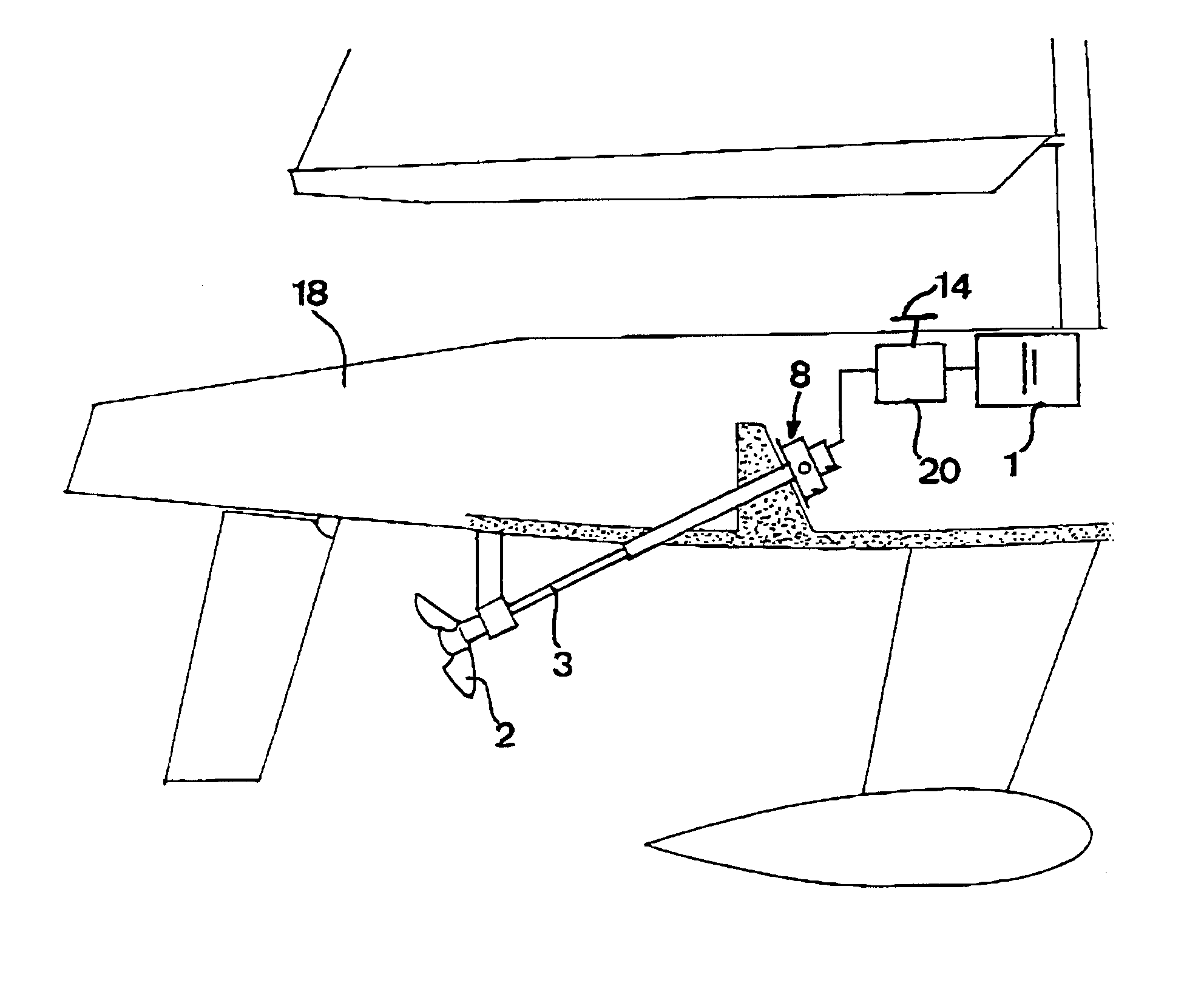
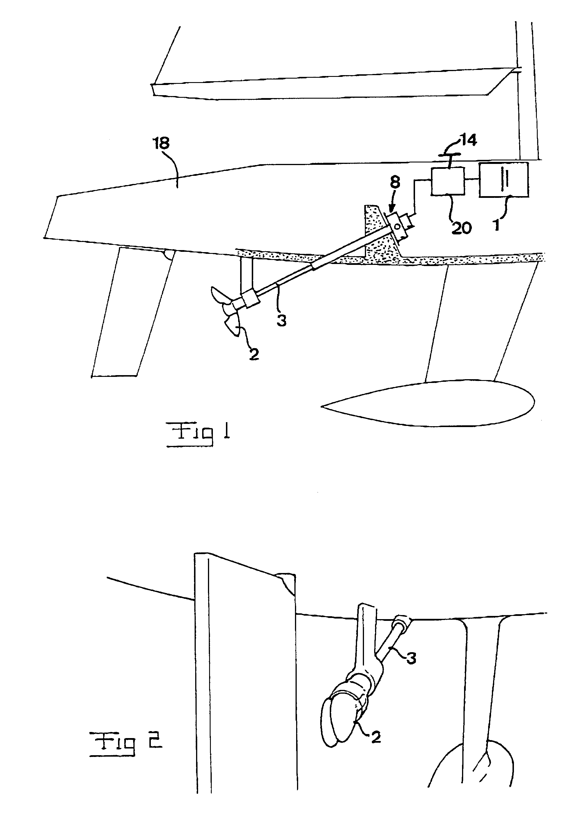
[0024]The overall construction of a device for charging at least one electric battery on board a boat is illustrated in FIG. 1. It is preferably a question of a plurality of 12 volts batteries 1 intended to be used both for propelling the boat 18 and for supply of electricity to other equipment on board, such as refrigerator, lightening, autopilote and the like. The device comprises a propeller 2 adapted to be immersed in water and then through the movement of the boat be driven to rotate an axle 3 connected thereto. The axle 3 is in its turn connected to a rotor of an electric direct current machine. The direct current machine is preferably a permanent magnet machine, but other types of direct current machines are also conceivable, even if a permanent magnet machine is very advantageous thanks to the high energy density thereof. Other conceivable electric direct current machines are series motors and shunt motors. Through the rotation of the rotor a voltage is as usual generated in...


PUM


Abstract

A device for charging at least one electric battery (1) on board a boat comprises a propeller (2) adapted to immersed in water through the movement of the boat be driven to rotate a axle (3) and an electric direct current machine (8) connected to the axle and adapted to generate voltage to the battery for charging thereof upon rotation of the axle. A DC / DC-converter (7) is arranged to convert the voltage generated by the electric machine through the rotation of the axle to a higher voltage suited for charging the battery. A member (10) is adapted to measure the voltage generated by the electric machine and a micro processor unit (9) is adapted to control the DC / DC-converter on the basis of voltage data delivered by said member.

Description

FIELD OF THE INVENTION AND PRIOR ART[0001]The present invention relates to a device for charging at least one electric battery on board a boat, which comprises a propeller adapted to immersed into water through the movement of the boat be driven to rotate an axle and an electric direct current machine connected to the axle and adapted to generate voltage to the battery for charging thereof upon rotation of the axle.[0002]It is of course possible to charge such a battery for using the electrical energy of the battery for all types of objects, but the case of utilizing this electrical energy for propelling the boat in question will hereinafter be discussed for illuminating the invention, but accordingly not in any way for restriction thereof. The boat is then preferably a sailing boat having an electrically directly driven propelling system, which makes it possible to generate electric energy through said propeller when sailing. It is conceivable to use the electrical energy for prope...

Claims


Application Information

Patent Timeline
Patent Type & Authority Patents(United States)
IPC IPC(8): F03B13/00B63H21/17B63J3/04H02J7/14
CPCB63J3/04H02J7/1415Y02T70/70B63J2003/046H02J2310/42Y02T70/00B63H21/17
Inventor LARSSON
Owner LARSSON
Learn More